This discussion is locked.
You cannot post a reply to this discussion. If you have a question start a new discussion

Minimum values of insulation resistance

What is the science behind the 1 MOhm minimum insulation resistance? What is the basis for this particular value?

  • Therefore each circuit can pass an insulation test, but the whole board can fail, so what do you do next?


    But there is no BS 7671 value for a single circuit to pass/fail - just one for the complete DB's worth - 1MΩ*


    If the whole DB fails, then it's a fail.


       - Andy.


    * for initial verification at least.

  • AJJewsbury:


    Therefore each circuit can pass an insulation test, but the whole board can fail, so what do you do next?


    But there is no BS 7671 value for a single circuit to pass/fail - just one for the complete DB's worth - 1MΩ*


    If the whole DB fails, then it's a fail.


       - Andy.


    * for initial verification at least.


    Regulation 643.2 says nothing about DBs


    The requirement is:


    643.3.2 The insulation resistance measured with the test voltages indicated in Table 64 shall be considered satisfactory if the main switchboard and each distribution circuit tested separately, with all its final circuits connected but with current-using equipment disconnected, has an insulation resistance not less than the appropriate value given in Table 64.


  • Regulation 643.2 says nothing about DBs


    It's implied - given 314.4 you've got to have a DB between the distribution circuit and the final circuits (OK I could have been clearer that it includes the sub-main as well as the DB and final circuits).


        - Andy.

  • AJJewsbury:


    Regulation 643.2 says nothing about DBs


    It's implied - given 314.4 you've got to have a DB between the distribution circuit and the final circuits (OK I could have been clearer that it includes the sub-main as well as the DB and final circuits).


        - Andy.


    I don't agree. What about installations with multiple levels of distribution?


    For example, even the simple case of Main three-phase switchboard feeds a number of three-phase boards, which in turn feed some equipment plus some single-phase boards. To comply with 643.2, the minimum requirement is for each of the following to be 1 MΩ (unless of course the entire switchboard with everything connected complies):

     - The main switchboard including any final circuits it supplied

     - Each distribution circuit of the main switchboard (individually) through the DB it supplies, having all final circuits connected, along with the sub-mains this DB supplies to the single-phase DBs, along with the supplied single-phase DBs with all final circuits connected.


    So, whilst all DBs will have to meet the requirement, in the case of the three-phase DBs in the tier above, their tests must include not only their submains and final circuits, but also the submains (and associated DBs and all of their final circuits) too.


  • mapj1:

    Is an NE fault immedately dangerous, potentially dangerous, or just extremely annoying if it causes nuisance tripping ?

    Personally, I think without another fault, such as an open CPC - which may come with the cable damage (rings are nice as you can test for that) or LN reversal, it is probably more of a pain  than an immediate  danger.


    In a TN-C-S or TN-S installation that is supplied in accordance with ESQCR, an N-E fault could be considered a breach of legislation, as both conductors effectively become parallel PEN conductors. In a TT system, an N-E fault alters the supply earthing arrangement, and again effectively could be considered a breach of legislation.


    The reasons I think it could be considered immediately dangerous are:

    (i) Permits diverted Neutral currents, potentially affecting touch voltages on exposed-conductive-parts, and possibly extraneous-conductive-parts.

    (ii) Uncertain behaviour of protective devices - especially RCDs.

  • I think those are 'potential' dangers. Diverted neutral currents flow up every water and gas pipe in some streets, without injury, as the DNOs do not distinguish between N and E, and in other parts of the world an NE bond would be permitted and in some cases required by regulation .

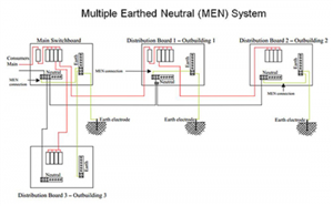
    Consider this little sketch of MEN wiring
    def624a26d54b2a5d2a02ea55ce7d6db-huge-men_wiring.png

    shamelessly pilfered from the   Q and A pages of the Australian National Electrical and Communications Association.   

    Here there is no CPC to the outbuildings 2 or 3, and an NE bond creates a local CPC.

    Personally I do not like it either, but equally they do not like our use of TT in that situation. However, if it was done that way here that does not make it immediately more dangerous then over there, just non-compliant with our regs, and, in the UK at least, illegal as well,  if you are a consumer of electricity and not a distributor. (But then plenty of UK sites with more than one LV transformer have an LV interconnection arrangement that in effect means more than one NE bond.)


  • mapj1:

    I think those are 'potential' dangers. Diverted neutral currents flow up every water and gas pipe in some streets, without injury, as the DNOs do not distinguish between N and E, and in other parts of the world an NE bond would be permitted and in some cases required by regulation .


    Agree that Diverted Neutral Currents is not always immediately dangerous. It could be difficult to quantify the risks in an installation that was not designed for it, though.


    When added to the potential for disrupting protective devices, however ...

  • I'm not saying an NE short is a good thing - far from it, but If all it does is lower R2 or trip an RCD prematurely above some modest level of load, then is only being a pain to the user, not the same 'immediate ' danger comparable to exposed live parts.

    Only a really badly designed system becomes dangerous in a power cut and I'd hope they have back up power or some pre-arranged back-up supply.

    And as noted above, when we started putting RCDs in, quite a lot of dormant N-E faults were found and had to be fixed, suggesting they had been around a while.

  • mapj1:

    I'm not saying an NE short is a good thing - far from it, but If all it does is lower R2 or trip an RCD prematurely above some modest level of load, then is only being a pain to the user, not the same 'immediate ' danger comparable to exposed live parts.


    I don't think RCD tripping prematurely is the only outcome. RCD not tripping at all is another possibility (but perhaps not too common thankfully).


    Only a really badly designed system becomes dangerous in a power cut and I'd hope they have back up power or some pre-arranged back-up supply.

    And as noted above, when we started putting RCDs in, quite a lot of dormant N-E faults were found and had to be fixed, suggesting they had been around a while.


    Agreed. However, we also need to bear in mind that if there's an undetected N-E fault, let's say on part of an installation not protected by an RCD, the first we'd know about it is when someone gets a belt from an exposed-conductive-part should the Neutral break.


  • gkenyon:


    Wombat:

    What is the science behind the 1 MOhm minimum insulation resistance? What is the basis for this particular value?


    It matches perfectly the permitted touch current for double insulated appliances (0.5 mA) for a supply voltage U0 of 500 V.


    For U0 = 1000 V, 1 MΩ would lead to a touch current of 1 mA (the accepted threshold of perception).


    These values align with Clause 5.2.7 in BS EN 61140 Protection against electric shock - common aspects for installation and equipment, which states the limit of steady-state touch current to be 0.5 mA AC or 2 mA DC (higher levels are permitted in some circumstances).


    In fact, there is some science behind these values, and they are based on the IEC 60479-series of standards Effect of current on human beings and livestock which is used as a reference standard for developing electrical safety standards - BS EN 61140 is itself based on this series of standards.


    Have just been going through BS EN 61140. Clause 5.2.7 has limitation of steady state touch current 
    a) For touch current, the following values are proposed:
    – a steady-state current flowing between simultaneously accessible conductive parts not exceeding the threshold of perception, 0,5 mA a.c. or 2 mA d.c. under normal operating conditions;
    – values not exceeding the threshold of pain 3,5 mA a.c. or 10 mA d.c. may be specified under abnormal or fault conditions.


    So if we are using the 1000VDC insulation resistance test voltage and minimum insulation resistance of 1MOhm we get a maximum allowable current of 1mA which is half the threshold of perception.

    In the real situation we would have a cable with 1MOhm resistance operating at 230VAC and giving a leakage current of 0.23mA, which is again half the threshold of perception.


    Looking at IEC/TR 60479*1 clause 5.2 the threshold of reaction is 0.5mA for ac and clause 6.1, 2mA for dc. This equates to the physiological effect "Perception possible but usually no started reaction" for ac and "Slight pricking sensation possible when making, breaking or rapidly altering current flow" for dc.


    An insulation resistance minimum of 500kOhms would still be within the Standard requirements. 


    Why then does BS7671 require 1MOhms for minimum insulation resistance?