The IET is carrying out some important updates between 17-30 April and all of our websites will be view only. For more information, read this Announcement

This discussion is locked.
You cannot post a reply to this discussion. If you have a question start a new discussion

TT systems and RCD trip times

Hi all


Just reading through the disconnection times in the regs and noticed something I've never thought of before.


On table 41.1 there is a note under the table that states that the disconnection times of a TT system can be the same as a TN system if disconnection is achieved by an OCPD and bonding is in place. However, I've not come across a TT system with a Ze low enough where only an OCPD can be used. The lowest Ze I've seen was 20 ohms.


Therefore:

On a TT system the disconnection times are 1 second and 0.2 of a second. Reg 411.3.2.2 & 411.3.2.4.

You would normally use an RCD for fault protection due to earth rod resistance causing higher than max Zs on final circuits as well as additional protection. Reg 411.5.3.


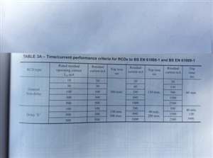
However, according to the OSG 11.2 and 11.3 the max allowable time to trip for a 61008 and 61009 can be up to 300ms (or, as stated, less then 300ms so 299.99ms).

If you are using RCBOs on circuits requiring 30mA protection and a selective type on the incoming it is 150 to 500ms on circuits without the RCBOs, so even worse.


This will mean it may not comply with the disconnection times. If you test the RCD and it trips within the 200ms it will comply but the fact that the BS standards allow for a longer time means that technically it does not comply.


(On a side note it seems strange that the older BS4293 RCD specifications do have a max trip time of less that 200ms, although it would still be the same issue with the selective type).


  • Ajjewsbury


    I think you may have misunderstood what I did.

    I was responding to lyledunn's post regarding how testers test at a current of x 1/2 before testing at the selected current setting. 

    So if a setting of 100mA was selected it would initially test at 50mA before doing the test whether set to x 1 or x 5.


    This is something I had never known testers to do before so I put it to the test.

    I was not testing on a TT system. I was trying out what he had said on a 30mA RCBO on a TN-S system, the socket circuit in my kitchen.


    So when it was set to 100mA at x 1/2 it sent 50mA. This tripped the 30mA RCBO and said "trp" as the tester correctly saw it as a fail.

    When set to 100mA at x 1 it sent 50mA first expecting no trip. However the 30mA RCBO did trip so it said "trp" as it was expecting a 100mA RCD not to trip before going on to test at 100mA.


    I would not have known this before as I don't tend to test 30mA RCDs with anything other than a 30mA setting unless the RCD is misbehaving, then I would use a ramp test.

  • On the VAR setting on the megger MFTs and maybe also on others, you use the 5 times setting. So, for example, if you have a 30 mA RCD and you want a 60 mA test current set VAR to 12.     5 x 12  = 60.  Or another example, you have a 100 mA RCD, you want 2 x In ( 200 mA ), again select 5 x setting , set VAR to  40 mA and bobs your Badger.
  • Alcomax


    You're and absolute genius.

    Works a treat. The VAR setting being set so low will only pretest with half of the VAR setting allowing testing without it displaying "trp".

    You can even set it to do an x 3 or x 4.


    However, it will only work on RCDs up to 100mA.

    Won't work on the MFT1711 for 300mA RCD as the VAR setting needs to be 120 and it only goes up to 100 when set to x 5.

    It goes up to 500 when set to x 1 but that's 100 short of 600 needed for the x 2 test.

    Don't know if other testers will allow the VAR to be set higher.


  • I think you may have misunderstood what I did.


    Ah yes - I think I probably did! Sorry.

      - Andy.

  • It goes up to 500 when set to x 1 but that's 100 short of 600 needed for the x 2 test.

    Don't know if other testers will allow the VAR to be set higher.


    500 mA should be more than enough to fire a 300mA RCD in < =200mS.  If not, then there will be something else wrong.  The "2 times" is arbitrary. The name of the game is that the RCD [ s type ] is quick enough.
  • If you are testing a 100 mA S-type time delayed RCD you need to use the correct test with the countdown timer, if you start fiddling about testing at x 0.5, x 1 and x 5 you will end up with different test results which are not correct, I have been told that by both RCD manufacturers, tester manufacturers and other reputable sources.


    100 mA RCDs are not being installed in the quantity that they used to be as lighting circuits and cables concealed in walls have virtually eradicated the installation of new split load consumer units with a 100 mA RCD main switch and a 30 mA RCD for sockets on the split, with people opting to install consumer units with 30 mA RCBOs or with dual  30 mA RCDs instead, though the technicalities of doing so is open to discussion.


    The outcome is that many electricians rarely, if ever, test time delayed RCDs so don’t concern themselves about the issues regarding testing them.

    17a55b727d9e8c65b1f509028daf6292-huge-d91aad8c-ee2f-4e7b-b916-d9b1298d4280.jpg


    Don't forget for time delayed RCDs there is a minimum trip time as well as a maximum trip time.


    Andy Betteridge
  • And testing Hager Type A 30 mA RCDs has not been mentioned. ?

  • The outcome is that many electricians rarely, if ever, test time delayed RCDs so don’t concern themselves about the issues regarding testing them.


    The OPs last issue was about achieving 200mS disconnection with an RCD tester with an S type on a TT system. If there is a final circuit protected by the s type, the 200mS may need to be demonstrated.

    If you are testing a 100 mA S-type time delayed RCD you need to use the correct test with the countdown timer, if you start fiddling about testing at x 0.5, x 1 and x 5 you will end up with different test results which are not correct, I have been told that by both RCD manufacturers, tester manufacturers and other reputable sources.


    Not necessarily so. The countdown test for S type is simply to check there is discrimination with down stream devices. It is more of a gimmick, as you would quickly find if there is no discrimination if you tested a downstream RCD first. Overall, a lot more efficient than waiting for the countdown test to do its thing.


    The Variable test [VAR] on megger [maybe others also] is designed to work with the 5x  , simply as you will mostly fall foul of the notional "fail" [ = "trp" ] if you try this on 1x.
  • The other issue is that when I did the testing course and we were told that we only test 30 mA RCDs at x 5, because generally shoving half an amp through a domestic earthing system and electrode to test a 100 mA RCD is getting risky.


    Andy B
  • And we should always carry out an earth loop test before doing a RCD test, bearing in mind I was using my Robin tester that doesn’t anticipate if the voltage on the earthing system and associated metalwork is going to go above fifty volts and abort the test like the modern testers.


    I can still get my old Robin to do some tests that my newer testers won’t do, but it doesn’t have a dedicated S-type RCD test.


    Andy B.