This discussion is locked.
You cannot post a reply to this discussion. If you have a question start a new discussion

Farm earthing arrangements.

009a7dbbf62372ab469269cf2662d114-huge-20200425_145756.jpg


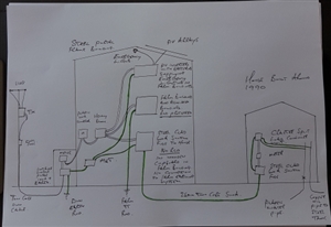
Some years ago I started doing electrical work at a farm, originally the farm buildings and house were both connected to the DNO earth terminal.


I altered it so that the farm buildings are TT , but left the house connected to the DNO earth terminal. The possible issues are that there is a steel clad switch fuse enclosure for the house inside a wooden cupboard in the farm workshop and the SWA cable for the house passes through the ground immediately adjacent to the farm building. But there was no physical connection between the house and farm earthing arrangements.


It had been like that for a few years as the house has not had any alterations at all, just a few repairs. So the house installation is effectively exactly the same as it was when the house and the farm buildings were thirty years ago and connected up as a new installation by the DNO.


However (you knew there was going to be a however!) a couple of years ago PV panels were installed on the farm building roof and the installers used the DNO and house earth terminal rather than the farm buildings earth terminal, despite the PV system being in and on the farm buildings and it having storage batteries that feed back into the both installations as they share a meter; and the storage batteries act as a supply to emergency lighting in the farm buildings when the installation is off-grid.


I am now reviewing the earth arrangements, the house is empty and needs tidying up, thirty two lights need replacing and odd repairs, there won't be any alterations it is just replacing fittings and replacing MCBs in the split load consumer unit with RCBOs to give additional RCD protection in the house. 


I will leave it at that and not express my thoughts, as it will be more interesting to see what your thoughts are rather than trying to get you to consider mine.


Comments please. 


Andy B
Parents
  • On the subject of PNB, it seems there are a number of variants.


    In the simple case - one transformer feeding one consumer with the electrode connected on the earth side of the N-PE link at the consumer's cut-out it is a nice simple TN-S system.


    There do seem to be other possibilities however. Engineering Recommendarion G12 (which is what think most DNO's policies are based on) seems to suggest that up to 4 consumers may be permitted to share the same transformer - but as there is still only one point where the N is deliberately earthed - there can't be an electrode at every one of the consumer's cutouts - but must presumably be at some common point upstream. There's no suggestion that there needs to be separate N and PE conductors downstream of the point the N is Earthed, so there would be a CNE or PEN between that point and individual consumers which then have both their N and PE connected to the supply CNE. This would seem to be TN-C-S (but not PME as there's no multiple earthing). Some DNOs seem to limit PNB to a single consumer - but not all it seems.


    Even when there is a single consumer there is also the possibility of the N earthing point being upstream of the consumer's cutout where the N-PE link is - which again would be TN-C-S rather than TN-S.


    WPD's document https://www.westernpower.co.uk/downloads/3293 seems to give a pretty comprehensive overview (especially appendix B) and seems to sum things up nicely with "Depending upon whether the earth connection to the customer is taken from the transformer neutral earth or from the neutral direct this can be viewed as either TN-S or TN-C-S.".


       - Andy.
Reply
  • On the subject of PNB, it seems there are a number of variants.


    In the simple case - one transformer feeding one consumer with the electrode connected on the earth side of the N-PE link at the consumer's cut-out it is a nice simple TN-S system.


    There do seem to be other possibilities however. Engineering Recommendarion G12 (which is what think most DNO's policies are based on) seems to suggest that up to 4 consumers may be permitted to share the same transformer - but as there is still only one point where the N is deliberately earthed - there can't be an electrode at every one of the consumer's cutouts - but must presumably be at some common point upstream. There's no suggestion that there needs to be separate N and PE conductors downstream of the point the N is Earthed, so there would be a CNE or PEN between that point and individual consumers which then have both their N and PE connected to the supply CNE. This would seem to be TN-C-S (but not PME as there's no multiple earthing). Some DNOs seem to limit PNB to a single consumer - but not all it seems.


    Even when there is a single consumer there is also the possibility of the N earthing point being upstream of the consumer's cutout where the N-PE link is - which again would be TN-C-S rather than TN-S.


    WPD's document https://www.westernpower.co.uk/downloads/3293 seems to give a pretty comprehensive overview (especially appendix B) and seems to sum things up nicely with "Depending upon whether the earth connection to the customer is taken from the transformer neutral earth or from the neutral direct this can be viewed as either TN-S or TN-C-S.".


       - Andy.
Children
No Data