This discussion is locked.
You cannot post a reply to this discussion. If you have a question start a new discussion

5 second disconnection times

Hi all


Something that I have always wondered about since I started doing electrical work.


The 0.4 and 5 second disconnection times. 0.4 makes sense as it is quick.

However 5 seconds still seems a long time for exposed conductive parts to remain live. When I first started, lighting circuits had a 5s time.

Now it's 0.4 for all circuits feeding socket outlets up to 63A but only for fixed equipment up to 32A. So any equipment over 32A can be 5s.

The reason given in collage was that it was portable equipment that can be picked up and gripped but fixed equipment can be pulled away from.

Previously, in 16th ed regs, the 0.4 was for socket outlets and circuits supplying equipment that can be hand held.

However, 5 seconds still seems a long time for exposed metalwork to be live. I know with a low impedance earth the voltage will be lower, but still.


The other thing is that even a distribution circuit that can have 5s dis time, on an earth fault, say in an armoured cable, all earthed metalwork can be live for the full 5 seconds, even hand held equipment on circuits with a 0.4s dis time. I realise that if the fault was on the actual item of equipment itself the voltage would be higher.


Any equipment, though, above 32A can still have a 5s dis time. I come across fixed equipment all the time that is above 32A. This equipment quite often has parts of it that can actually be gripped. When the body has electricity passing though it the muscles contract so it may be hard to pull away.

I've seen a video of three men pushing a tower hitting an overhead HV line. all three dropped down but their hands still gripped the scaffold poles.

I know were dealing with LV but the muscles still react the same.

Even showers could once have a 5s dis time and the only thing that has changed that is the regs for RCDs in rooms containing a bath or shower. It's still on a circuit that, without the RCD, allows 5s.


The fact that the regs have tightened up of what circuits can have 5s dis times shows that there is still a danger on 5s. Otherwise, why change them to 0.4s.


Any thoughts?


  • 230V supply.


    • 1.5 sqmm cable has 1.0 sqmm CPC   touch voltage on fault  becomes 138

    • 2.5 sqmm cable has 1.5 sqmm CPC   touch voltage on fault  becomes  144V

    • 4 sqmm cable has 1.5 sqmm CPC      touch voltage on fault  becomes  167V

    • 6 sqmm cable has 2.5 sqmm CPC  touch voltage on fault  becomes 162V

    • 10 sqmm cable has 4 sqmm CPC    touch voltage on fault  becomes  164V

    • 16 sqmm cable has 6 sqmm CPC  touch voltage on fault  becomes 167V


    But that only holds entirely true if the entire earth fault loop consists of that type of cable - which typically it isn't. For a PME system for example you'd have a full sized PEN making up the 'Ze' part of the circuit - so diluting the increased voltage somewhat. Then you'd likely have main bonding at the intake which should in theory (and to some extent in practice) remove the p.d. along the supply PEN from what someone in the installation is exposed to. Actual numbers will vary considerably from each installation and fault to the next - but the general assumption seems to be that the mitigating factors like these usually balance out the increased voltage differences from the reduced c.p.c.s and so the 0.4s for 120-ish volts is still 'reasonable'.


       - Andy.

  • AJJewsbury:


    230V supply.


    • 1.5 sqmm cable has 1.0 sqmm CPC   touch voltage on fault  becomes 138

    • 2.5 sqmm cable has 1.5 sqmm CPC   touch voltage on fault  becomes  144V

    • 4 sqmm cable has 1.5 sqmm CPC      touch voltage on fault  becomes  167V

    • 6 sqmm cable has 2.5 sqmm CPC  touch voltage on fault  becomes 162V

    • 10 sqmm cable has 4 sqmm CPC    touch voltage on fault  becomes  164V

    • 16 sqmm cable has 6 sqmm CPC  touch voltage on fault  becomes 167V


    But that only holds entirely true if the entire earth fault loop consists of that type of cable - which typically it isn't. For a PME system for example you'd have a full sized PEN making up the 'Ze' part of the circuit - so diluting the increased voltage somewhat. Then you'd likely have main bonding at the intake which should in theory (and to some extent in practice) remove the p.d. along the supply PEN from what someone in the installation is exposed to. Actual numbers will vary considerably from each installation and fault to the next - but the general assumption seems to be that the mitigating factors like these usually balance out the increased voltage differences from the reduced c.p.c.s and so the 0.4s for 120-ish volts is still 'reasonable'.


       - Andy.


    What if the circuit supplies equipment outside of what we used to call the equipotential zone ?


  • mapj1:


    TT is not really much worse.


    Within what we used to call an equipotential zone, TT performs much better, and touch voltage is very small. Outside of that artificial construct, the touch voltage in a fault in TT systems approaches U0

  • Nicely done, all respondents! Thank you.


    Sparkymania.

    "intensité du courant", hence the symbol I, is an origin I only realised in the last year or few, when I saw a quotation from Ampère (some 200 years ago) about the two essential features of electricity: tension et intensité.  I'd occasionally wondered, before that.


    mapj1:

    As your list of FTE conductor-sizes implies, the 4 mm^2 is a particularly extreme case. I chose the 32 A rating to try to push the reader into this size, without going up to such high ratings (e.g. 16 mm^2) that the 0.4 s requirement mightn't apply. I'm ashamed to say I didn't even notice the need for an erratum in your first post - but might have done if wandering back.


    AJJewsbury:

    Good point - I specified (indirectly) the external loop impedance in order to ensure that the final-circuit cable would be the major part of the total, so that the voltages from mapj1 would be roughly right.


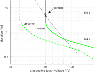
    I couldn't post the actual document of the retired IEC technical report I mentioned, but the following may be of interest, at least about my 'Q1' although  not the OP.  It is a plot I made for an instructive purpose, including the "L" and "Lp" curves defined in that IEC report. 


    The solid green "L-curve" is defined in the report (perhaps elsewhere too?) based on assumptions of (1) a time-versus-current curve rather below the threshold of danger indicated in IEC 60479-1, and (2) a particular case of skin contact based on normal, non-wet conditions.  The latter, I feel, is the weaker assumption. It's admittedly quite pessimistic for the stated sort of condition, as it uses values of resistance that the great majority of tested people actually exceeded. But there are doubtless plenty of "normal" situations where people actually aren't so dry.  Note that the body (contact) resistance itself can change with voltage as shown also in IEC 60479-1, which is taken into account here.  (For bigger or wet contact areas the voltage-dependence is less, so it's not a huge influence here. But for small dry contacts, like a wire-end on a hand, the resistance can zonk down by more than an order or magnitude if the contact point gets much of the 230 V compared to, say, 100 V: I've tested this first-hand, having first been a little suspicious.)  The Lp-curve is for 'particular' conditions, i.e. not dry. The other clutter is the 0.4 s limit that is used as a simplification for systems above 120 V and up to 230 V to earth, the 5 s limit that's the subject of this thread, and then some funny line and point I've derived from a bonding requirement ... I can look up what I based it on if anyone really wants to know, but I don't have it in my mind just now.

    3808d58f8f69dc6f0140c770dd9c3007-huge-t-vs-v__lcurve_etc.png


    Now the final part of the process:  the 0.4 s is based on the L-curve together with the assumption that a person is exposed to about 80% of 50% of the voltage to earth. This is 92 V, the corresponding time for which is rounded down to a neat 0.4 s. The 50% is based on equal ratios of line and protective conductor resistance in the final circuit. The 80% is based on the point made by AJJewsbury, where halving of voltage in the final circuit isn't the only factor in the voltage exposure. Increase of 230 V to the high end of the permitted range isn't done here (but 10% increase would be compensated by the rounding down to 0.4 s).


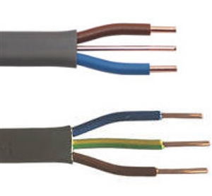
    The main point of my Q1 is that the 0.4 s certainly isn't based on the ratio of conductor sizes found in UK FTE cable design.


    [IEC TR 1200-413 1996] 413.1.3 says: "Table 41A of IEC 364-4-41 specifies a single time of 0.4 s. This time corresponds to a mean value of the factor c of 0.8 and a ratio m of 1, values which exist in general in final circuits. This time is confirmed by long experience in many countries as providing satisfactory protection against electric shock."

    To clarify: the factor 'c' describes the relation of impedances up- and down-stream of the bonding closest to the final circuit; and the factor 'm' is the ratio Rpe/Rl in the final circuit.  From mapj1's numbers, m=2.7 would be more appropriate to FTE "4mm^2" UK cable.  (What's the situation in Ireland? Rpe=Rl ?)


    [IEC TR 1200-413 1996] 413.1.3.5.  "The limitation to 5 s is conventional."  (And reasons justifying the longer time are given as the lower probabilities of faults in such circuits or of persons being in contact with or particularly gripping such equipment, and the hope that main bonding will suitably reduce touch voltage.  Just as already mentioned on this thread.)

  • Nathaniel, the reference to Irish T/E comes from the requirement for the cpc to be sleeved and same size as live conductor. This was introduced in amendment 2.2 to ET101: 2008 in 2017. The newly issued IS10101:2020 replaces ET101 2008 but I cannot find any reference relating to the requirement. The selection or calculation methods used appear to be the same as BS7671.
  • Thanks, Lyle - I saw lots of grey FTE-looking stuff snaking around the walls of a friend's new (self-)build in Ireland a few years ago, and assumed it was just the same stuff as I was used to. It sounds as if it would have been then, but wouldn't be in a new build now. Thanks to Screwfix's different sites, I see it's still FTE (in contrast to common continental round-section cables).
    f4cdcd6b7914fe3dcbcc6e6aeb2c6db2-huge-ae.jpg


    Distribution circuits may justify undersizing by the assumption of bonding, but I suspect the history of FTE undersizing in final circuits in the UK is a historic remnant from when earthing was expected to prevent something remaining live but not necessarily to make it 'safe' if touched during the short time before the fault was cleared. Presumably the probabilities involved (fault together with good contact with different conductive parts), together with the margins in the assumptions, have avoided any, or conspicuously many, fatal results.

  • I must admit I can see why Europe and others are not keen on our reduced cpc idea in T & E, not too fond of it meeself even 120V can still be severe
  • Do not be too sure that it is only final circuits that have reduced earth cross-section  - there are plenty of flats on sub-mains of 16mm T&E, especially where older buildings have been converted to bedsits and so on. The good news is that the plumbing is probably plastic.

    There are also plenty of older  street main cables where the earthing has partly or totally rotted off - quite often the fix is for the DNO to offer to convert to PME, or if the cable is really unsuitable for that,

    then just to tell you you need to go TT.
    97504b37d918a3b6835142fac8023c82-huge-ukpn_letter_bw2.png


  • gkenyon:
    Within what we used to call an equipotential zone, TT performs much better, and touch voltage is very small. Outside of that artificial construct, the touch voltage in a fault in TT systems approaches U0


    I wasn't aware that it is no longer called the equipotential zone. The fact that you used the expression "what we used to call" indicates that there is no description for it but it must still exist. 


  •  

    I wasn't aware that it is no longer called the equipotential zone. The fact that you used the expression "what we used to call" indicates that there is no description for it but it must still exist.


    I think it's just an admission that bonding doesn't create equipotentiallity - the laws of physics get in the way as bonding conductors don't have negligible impedance and the voltage difference along a c.p.c. during an earth fault (giving the potential difference between an exposed-conductive-part and extraneous-conductive-parts can be very significant.

       - Andy.