This discussion is locked.
You cannot post a reply to this discussion. If you have a question start a new discussion

5 second disconnection times

Hi all


Something that I have always wondered about since I started doing electrical work.


The 0.4 and 5 second disconnection times. 0.4 makes sense as it is quick.

However 5 seconds still seems a long time for exposed conductive parts to remain live. When I first started, lighting circuits had a 5s time.

Now it's 0.4 for all circuits feeding socket outlets up to 63A but only for fixed equipment up to 32A. So any equipment over 32A can be 5s.

The reason given in collage was that it was portable equipment that can be picked up and gripped but fixed equipment can be pulled away from.

Previously, in 16th ed regs, the 0.4 was for socket outlets and circuits supplying equipment that can be hand held.

However, 5 seconds still seems a long time for exposed metalwork to be live. I know with a low impedance earth the voltage will be lower, but still.


The other thing is that even a distribution circuit that can have 5s dis time, on an earth fault, say in an armoured cable, all earthed metalwork can be live for the full 5 seconds, even hand held equipment on circuits with a 0.4s dis time. I realise that if the fault was on the actual item of equipment itself the voltage would be higher.


Any equipment, though, above 32A can still have a 5s dis time. I come across fixed equipment all the time that is above 32A. This equipment quite often has parts of it that can actually be gripped. When the body has electricity passing though it the muscles contract so it may be hard to pull away.

I've seen a video of three men pushing a tower hitting an overhead HV line. all three dropped down but their hands still gripped the scaffold poles.

I know were dealing with LV but the muscles still react the same.

Even showers could once have a 5s dis time and the only thing that has changed that is the regs for RCDs in rooms containing a bath or shower. It's still on a circuit that, without the RCD, allows 5s.


The fact that the regs have tightened up of what circuits can have 5s dis times shows that there is still a danger on 5s. Otherwise, why change them to 0.4s.


Any thoughts?


  • Former Community Member
    0 Former Community Member
    Has nothing to do with bonding, equal potential, practicality, fire only mitigation or any such compromises. It comes from the fact the supply transformer (or generator) is not an infinite source. Fault current will always pull down the voltage at the spades of the transformer in varying degrees. As such normal Uo will not be present at the source during a fault resulting in a lower voltage to remote earth at the midpoint of the resistive divider than is otherwise being assumed.


    1.5, 2.5 and 4mm2 circuits present more impedance (lower current draw) than a 50mm2 circuits. Assuming equal live and earth in both cases the prior results in only a slight dip at the source (185 volts) leading to 92 volts to remote earth, while the latter results in a very large dip (80 volts) leading to 40 volts to remote earth. 


    When looking at these voltages in relation to time, they align perfectly with the IEC body graph with room to spare.

  • Former Community Member
    0 Former Community Member


    V fault = Vsupply *(Rlive /(Rcpc +Rlive))


    230V supply.
    • 1.5 sqmm cable has 1.0 sqmm CPC   touch voltage on fault  becomes 138

    • 2.5 sqmm cable has 1.5 sqmm CPC   touch voltage on fault  becomes  144V

    • 4 sqmm cable has 1.5 sqmm CPC      touch voltage on fault  becomes  167V

    • 6 sqmm cable has 2.5 sqmm CPC  touch voltage on fault  becomes 162V

    • 10 sqmm cable has 4 sqmm CPC    touch voltage on fault  becomes  164V

    • 16 sqmm cable has 6 sqmm CPC  touch voltage on fault  becomes 167V


    All more than 120V...


    More likely around this:


    V fault = Vsupply *(Rlive /(Rcpc +Rlive))


    230V supply.


    • 1.5 sqmm cable has 1.0 sqmm CPC   touch voltage on fault  becomes 110V

    • 2.5 sqmm cable has 1.5 sqmm CPC   touch voltage on fault  becomes  95V

    • 4 sqmm cable has 1.5 sqmm CPC      touch voltage on fault  becomes  88V

    • 6 sqmm cable has 2.5 sqmm CPC  touch voltage on fault  becomes 70V

    • 10 sqmm cable has 4 sqmm CPC    touch voltage on fault  becomes  64V

    • 16 sqmm cable has 6 sqmm CPC  touch voltage on fault  becomes 50V

  • I agree the neighbours lights dim  a bit during faults but in a built up area of the UK I'd disagree slightly with your assumptions about supply droop being dominated by the transformer.  The reactance of the substation transformer is such that we see less than 5% drop at full load, and the substation may be a 500kVA unit. In that sense the short circuit KVA would be 10MVA mark.

    L_E  fault current would be ~ 10E6 ÷ (400 × 1.73) = 15 kA  (lets call that 16 milliohms )

    The impedance at that point is mostly inductive, but the thing that lowers the PSSC a lot, and makes it more a or less resistive  impedance at the consumer unit is the street cables, the 50m or more of 186mm or 300mm coming down the roadside is perhaps 5-10 milliohms and then the  10m to 20m or so from there in 35mm to the cut out is more like 30-60 milliohms. By this time we are at perhaps 0.1 ohms and  a PSSC of less than a couple of kA.

    Given 1mm2 cable (lights) is 32 milliohms there and back per metre you only need a 5 to 10  metres of that sort of final circuit between the consumer unit and the fault, and practically all the VD is in the final circuit. For a circuit wired in 10mm2 it would be ten times further. The reduced diameter earth core in the T and E is a really significant effect, as the VD in the cable is more so than the depression of the supply or the neutral lift.
  • ProMbrooke:


    More likely around this:


    V fault = Vsupply *(Rlive /(Rcpc +Rlive))


    230V supply.


    • 1.5 sqmm cable has 1.0 sqmm CPC   touch voltage on fault  becomes 110V

    • 2.5 sqmm cable has 1.5 sqmm CPC   touch voltage on fault  becomes  95V

    • 4 sqmm cable has 1.5 sqmm CPC      touch voltage on fault  becomes  88V

    • 6 sqmm cable has 2.5 sqmm CPC  touch voltage on fault  becomes 70V

    • 10 sqmm cable has 4 sqmm CPC    touch voltage on fault  becomes  64V

    • 16 sqmm cable has 6 sqmm CPC  touch voltage on fault  becomes 50V


    Yes but ... that only works indoors. And even there, slightly over 70 V is too much for 5 s ... perhaps even 1 s.


    What about when you supply equipment outdoors, and have no control over the voltage at a person's feet as you might have within a building (what we used to term "equipotential zone")?


    The worst case is a TT system, because the full U0 is available outdoors, and 1 s is way too long.


    Next up comes a TN-S system where the installation is some distance from the transformer supplying it.


    The actual answer, as Mike alluded to, is that it's an engineering compromise between what's practicable, and the likely risk of shock in a fault condition (larger conductors perhaps less likely to break, often in more robust wiring systems etc.).


  • ProMbrooke


    Your equation and results do not make sense, perhaps you would like to correct the error in your potential divider equation, obvious because increasing the conductor size from 2.5 to 4.0 mm LOWERS the touch voltage. I will leave the correction to the student.
  • Former Community Member
    0 Former Community Member
    I agree that it won't always be dominated by the transformer, but as you place current on the output terminals voltage will begin to drop. 230 vs 200 vs 150 volts between the X1 and X0 terminals is enough to make a significant time difference in the body graph when dealing with a hand to foot resistance of resistance of 1000 ohms. Especially when the IEC assumes that body resistance itself will change based on contact voltage.


    Supply transformers are becoming larger through out the world and I think this is why IEC-60364-4-41 now requires the 0.4 second disconnection time be extended socket circuits up to 63 amps.


    Regarding the UK that would be correct, however it still works out by leaps and bounds vs the minimum requirments of BS7671 or table 41.1.  Disconnection times (0.4 and 5s) can not be met or achieved via the thermal element in UK/EU MCBs and hence rely on the magnetic (solenoid) trip function. This means that even the max listed EFLI values for type B-D 125 amp MCBs will result in disconnection faster than 0.1 seconds. This leaves us with fuses/devices 125 amps and over which typically have a Zs of <0.25 ohms. Going by ohms law 0.2 gives us 265kw or 1,150 amps with an infinite source. A 250kw rated heater being placed across any phase and earth will result in a measurable drop in output voltage on a 5% Z 166kva transformer (assume the 500kva unit is a bank of 3 166kva units). Transformer voltage regulation is excellent at unity power factor, however sharply declines with lagging power factor. Reactance begins to dominate as you go up in wire size, so where as a 1mm2 lighting circuit will be seen as almost a purely resisitive load (during a fault), a circuit over 63 amps will dedicate at least half or more of its fault current to maintaining the magnetic field around each conductor. Consider current division and open over head conductors in the fault loop and XL dominates substantially.


    Try this, play around with the slides in relation to lagging loads vs unity loads to give you an idea:


      https://voltage-disturbance.com/power-engineering/transformer-voltage-regulation/


    Lastly consider that a final circuit is Zs=Ze+(R1+R2)... part of a whole when wiring a building...  meaning sub circuits from board to board are rarely run to their maximum EFLI having to of a low enough Z to allow for the final circuits to be long enough to hit all the devices through out. 


    In summary faults will either disconnect in less than 0.1 seconds, or result in significant voltage drop through the transformer making fault point voltage to remote earth minor.
  • Former Community Member
    0 Former Community Member
    kenyon

    Yes but ... that only works indoors. And even there, slightly over 70 V is too much for 5 s ... perhaps even 1 s.


    What about when you supply equipment outdoors, and have no control over the voltage at a person's feet as you might have within a building (what we used to term "equipotential zone")?


    The worst case is a TT system, because the full U0 is available outdoors, and 1 s is way too long.


    Next up comes a TN-S system where the installation is some distance from the transformer supplying it.


    The actual answer, as Mike alluded to, is that it's an engineering compromise between what's practicable, and the likely risk of shock in a fault condition (larger conductors perhaps less likely to break, often in more robust wiring systems etc.).


    In all of this I am assuming remote earth and a minimum body impedance of 1000 ohms. Zero bonding or equal potential taken into account.


    I'm well aware the IEC used to allow (and still does to a degree) equal potential bonding as a means to manage greater disconnection time however this is not what I have in mind.


    In a TN system voltage from the fault point to remote earth is far lower than is being assumed here. The transformer is far from an infinite source, it is rather weak.


    It has nothing to do with compromise, rather the IEC knows voltage and body resistance will typically never reach values that will violate the IEC's body graph.


    I'm going to go out and say that with circuits protected over 200-400 amps could easily get away with a 10 second disconnection time and this should be researched/considered further.  


  • Former Community Member
    0 Former Community Member
    davezawadi (David Stone):

    ProMbrooke


    Your equation and results do not make sense, perhaps you would like to correct the error in your potential divider equation, obvious because increasing the conductor size from 2.5 to 4.0 mm LOWERS the touch voltage. I will leave the correction to the student.


    This is key:


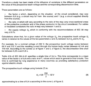
    4c0207d3ba6183b6a707d6d95fda5528-original-image-20210319053948-1.png


    Notice the assumption of C=0.8, meaning that on circuits 32 amps and under it is assumed the voltage at the source could dip to 184 volts or 80% of nominal, or at least 90% of nominal if part of C comes from being inside a structure with metal enforcments connected to the MET.


  • But that factor of 2 in the denominator of your equation 8 should be more like 1.5 in the case of twin and earth. Experience in the rest of Euroland is not so relevant here - in the UK our final circuits do not have full sized CPCs,  (nor do quite a few in-building sub-mains either) and in built up areas we may have larger lower impedance transformers, indeed in parts of London 1MVA transformers are meshed and the LV network in the streets is not even fused (AKA "the solid system"). Then there are a great many tower blocks with a megawatt transformer in the basement, and then bigger office and mixed use buildings with HV going up to a transformer on every 5th floor or so (look at Canary Wharf for an example of that if you like)

    In such cases your assumption that the supply droop has a dominant effect is not appropriate - it is mostly in the cables.

    Note that just because something is written by a committee does not make it infallible - look at the number of times the regs get updated for proof of that. ( I've sat on telecoms standards meetings, I know how it works, and it has perhaps made me slightly cynical. )

    I agree the incoming voltage will droop very significantly during fault for those rural sites fed by smaller (100kVA and down) pole-pig transformers, but they are more commonly earthed as TT anyway.

    I'm not sure we should underestimate the touch voltages to city dwellers by assuming that all installations are like that.

    There is an additional complication in a PME system, as the live voltage goes down the neutral comes up to meet it, so you have to be clear if you mean touch voltag relative to the CPC of the system, or to terra-firma earth voltage either at ground level as on incoming telephone cables etc.

    M.
  • Former Community Member
    0 Former Community Member
    mapj1:

    But that factor of 2 in the denominator of your equation 8 should be more like 1.5 in the case of twin and earth. Experience in the rest of Euroland is not so relevant here - in the UK our final circuits do not have full sized CPCs,  (nor do quite a few in-building sub-mains either) and in built up areas we may have larger lower impedance transformers, indeed in parts of London 1MVA transformers are meshed and the LV network in the streets is not even fused (AKA "the solid system"). Then there are a great many tower blocks with a megawatt transformer in the basement, and then bigger office and mixed use buildings with HV going up to a transformer on every 5th floor or so (look at Canary Wharf for an example of that if you like)

    In such cases your assumption that the supply droop has a dominant effect is not appropriate - it is mostly in the cables.

    Note that just because something is written by a committee does not make it infallible - look at the number of times the regs get updated for proof of that. ( I've sat on telecoms standards meetings, I know how it works, and it has perhaps made me slightly cynical. )

    I agree the incoming voltage will droop very significantly during fault for those rural sites fed by smaller (100kVA and down) pole-pig transformers, but they are more commonly earthed as TT anyway.

    I'm not sure we should underestimate the touch voltages to city dwellers by assuming that all installations are like that.

    There is an additional complication in a PME system, as the live voltage goes down the neutral comes up to meet it, so you have to be clear if you mean touch voltag relative to the CPC of the system, or to terra-firma earth voltage either at ground level as on incoming telephone cables etc.

    M.


    I agree, but remember, with MCBs you'll be hitting the instantaneous function even on your maximum permitted Zs. Only larger circuits (over 125 amps) will take time clearing, and those will cause at least some dip even on 1 MVA units. As such I still maintain the the source has a moderate to major effect on touch voltage.


    London like France, New York, Chicago ect are exceptions though. These networks, in particular Con Edison's networks, can be regarded as being almost truly infinite. Evidenced by 500MCM (253mm2) cables burning clear in manholes with only mild, local dimming of lights. At the same time remote earth becomes far more scarce- sidewalks, poor conductive floors, bonded pipes and building steal all work to reduce touch voltage. The scenario of being outside on damp ground while holding a metal tool or electric grill in the back yard like out in the country become very slim. 


    I will agree with you that technical committees get it wrong or in the case of today influenced by the manufacturers, however I still hold the belief that 5 seconds is unlikely to present a danger in most cases.