This discussion is locked.
You cannot post a reply to this discussion. If you have a question start a new discussion

LED Lighting Columns Inrush Current

I am looking at installing around 21 LED Lighting Columns to a Car Park. It states on the product data sheets that the Lamp Heads are 890mA / 68watts each (I think the 890mA refers to the output current of the driver and not the input current which will be nominally P/V excluding the efficiency of the driver). I have checked all the volt drops and cable calcs which have calculated out at 6mm 3core SWA buried underground. I am splitting the Lighting columns up into circuits and I would prefer to have 7 columns on each circuit. From the information provided on the data sheet it states that the inrush current is 57Amps per column which does seem a little high considering such a small load. This would mean when I select a suitable Overcurrent Device from BS7671 Time Current Curve Charts to withstand the 57Amps x 7 Columns = 399Amps inrush current. Full Load Current being 68Watts x 7 = 476Watts equates to around 2Amps. As 57Amps inrush is quoted (sum of + 399Amps) for the one Lighting Column then the following is concluded:

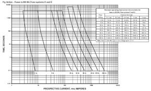
Assuming a 10Amp Type B – this would be not suitable as this device can only withstand 50Amps up to 5 Seconds so it will cause an instantaneous trip (this would normally be the device i would choose as default)
Assuming a 10Amp Type C – Suitable for a max of 1 Lighting Column as this device can only withstand 100Amps up to 5 Seconds so it will cause an instantaneous trip with 2 Lighting Columns wired on the one circuit
Assuming a 10Amp Type D -  Suitable but only for a max of 3 Lighting Columns as this device can only withstand 200Amps up to 0.4 Seconds and withstand up to 100Amps over 5 Seconds so it will instantaneously trip with more than 3 Lighting Columns wired on the one circuit (i would usually use Type D only on motor circuits and not the usual device of choice for protecting Lighting Circuits)

Deduced from the data sheet and if all is correct, we could only wire a maximum of 3no Lighting Columns per circuit but this using a Type D Overcurrent Device to be sure no tripping will occur during initial spike. This has confused me slightly because I have never seen such high inrush currents like this for such small LED Lighting Loads.

I wondered if any Electrical Designers/Electricians had queried this before with manufacturers and also whether i am missing something. One would expect you could have 7 Columns per circuit as such a small load of 2Amps but the inrush would surely take out the protective device ?   

  • We would usually use a “public lighting cutout” in each column, to fuse down to the right value, then run a distribution circuit looped through the cutouts. The PL cutouts are designed to have an SWA in and an SWA out as well as a fuse or mcb  for the column, so no buried joints - makes later fault finding easier. 


    Regards,


    Alan.
  • Good shout. I do plan to use cut-outs also for local isolation/maintenance which i didn`t make clear at the start. I have looked at DP Tofco Cut Outs (Other manufacturers are available) located in each Lighting Column comprising individual 6A fuses to BS88-2. The problem is that the 6A fuses according to BS7671 Time current curves table Fig 3A (3 a) states they will withstand up to 36A up to a maximum of 0.1 second. Next size up fuse is 20A BS88-2 which will withstand 180A for 0.1 second. A 20A device means i lose the discrimination/selectivity. If i up the over current device protecting each circuit from 10A to 20A to keep selectivity compliant then the cables to the Lighting Columns become very large feeding each cut out ie from 6mm SWA to 16mm due to VD so not ideal and costly -  if that makes sense.
  • Here is the curve chart 
    ed7f563b8605614b497e59cf851f6dc1-original-image.png
  • not sure about outdoors but indoors you'd consider inrush limiters- a series device that behaves like a resistor when cold and limits the current, and self heats and warms up and the resistance then falls to a few hundred milliohms over a fraction of a second. Also used for soft start in things like computer power supplies.
    an example 80 ohms cold, falling to a fraction when warm - inrush 3A max..


    I have installed things similar to this to limit inrush in boxes with transformers of a few KA with them on ceramic choc block in a adaptable boxes to elimiinate a problem of lights flicker and audio thump when power in. 20 yeasrs on they are still working..


    Pity the LED makers did not consider it.

  • Great shouts. This might be the answer, just found that the BS88-2 (Bussman as an example) make a 10A version which shows can withstand up to 60A up to 0.1 secs. This should hold 57A spike per Column. 

    4cfab5e6a0148b98e47b195764181fae-original-image.png
  • I strongly suspect that the quoted 890ma per lighting unit is the mains input current, and not the output current into the LED array. This figure is far in excess of that suggested by the wattage, due to the very odd waveform of the current.


    I would consider controlling each lamp by its own photocell as in public lighting practice. This will avoid any concerns regarding cumulative inrush current from switching them as a group. Manufacturing tolerances and slight differences in exposure to daylight at each unit will ensure that starting is spread over some minutes.


    If central control is essential, then fit each lamp with a street lighting cut out and a 6 amp fuse. Protect the cable with a large fuse able to withstand the combined inrush current. This fuse need only provide short circuit protection, overload protection being not required due to the nature of the load.

    Remember that the inrush current will be somewhat reduced by the cable impedance.
  • I have allowed for DP cut-outs so hopefully all is good. The lighting is to be wired on an autonomous system with independent PIR sensors. The autonomous system controls the light output of the lamps depending on inputs from PIR sensors which react to movement in the area of those sensors. The lamps can be programmed with two profiles, a low light level for idle when no movement is detected and another higher light level event profile when the sensors are triggered. Both of these profiles can be adjusted through the night to reduce the lighting levels for example after midnight if usage is expected to reduce significantly. The rate at which the light output changes from idle to dim and vice versa can be changed, as can the length of time the light output is set to maximum after a trigger. When movement is detected by a sensor, a wireless signal is sent to all of the lamps which are programmed to react to this sensor. Any lamp / luminaire can react to up to 15 sensors. Typically a sensor will trigger luminaires positioned up to two or three columns distant from any given sensor.
  • Former Community Member
    0 Former Community Member
    Probably worth pointing out that the inrush current, whilst reasonably large, is also very short lived - the manufacturers data probably says it's something like 57A but that is only likely to exist for about 150 microseconds - ie about 0.00015 seconds.


    This is so short as to make time current curves almost useless, you need another approach such as:


    Wire the circuit to your proposed column groups (7No) in say 6.00mm2 and protect with a 63A fuse (you aren't worried about overload protection at this point - only short circuit and inrush protection)


    Put a 10A fuse in the cut out assembly to manage the inrush of the single lamp and to act in concert with the other columns for overload protection of the circuit (you are assuming here that you won't get the same overload fault on every column simultaneously)


    You could run a 3 phase circuit around every column to 3 phase cut outs with the luminaire connected on the relevant phase to the cut out (or as Alan suggested, loop a single phase circuit and use 3 circuits)


    In practice, the very short duration of inrush at 0.001 seconds as a very conservative upper bound, won't ever trouble a MCB which usually has a minimum time to operate of around 0.01 seconds (ie 10 times longer) - consequently you are very unlikely to delatch an MCB - but fuse technology in this application is preferable


    Regards


    OMS


  • Thanks all that`s great info. Presumably you mean to protect with a 6A fuse not "63A fuse" ? Anyhow I have done exactly that albeit using 6Amp single phase circuits now feeding a max of 3no columns per circuit. They are fairly long runs in different directions so this keeps VD to a minimum too and easier all round. Not keen on the idea of running 3 phase looping in at the metal lighting columns particularly in public places tbh - just my preference and avoids any 400v potential if a fault occurs at a column then the risk is reduced with 230v as a pose to 400v. All Column circuits will go back to a mains enclosure, it`s TT 400A. There are also 20EVC`s hence the reason for the large incoming supply. Main switch is a 400A 300mA (damn expensive but satisfies TT requirement) with earth spike or condudisc at the origin. Trying to work out whether we go earth spike or condudisc but had no experience of using condudiscs so may play safe with spike.
  • Former Community Member
    0 Former Community Member
    I did actually mean a 63A fuse


    In terms of your 6A Type C, then that has an instantaneous trip of 6 x 5 = 36A, allowing for a crest factor of say 1.404 = 50.5A - so that's still shy of the theoretical inrush of 57A


    For a fault to earth, on a 3 phase 400V system you still only have 230V - so you may want to consider that


    I had to google "condudisc" - I hope you aren't paying a lot for them !!


    Regards


    OMS