This discussion has been locked.
You can no longer post new replies to this discussion. If you have a question you can start a new discussion

Unusual MCB

Here's an interesting one.

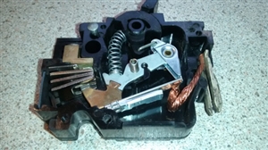
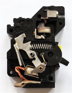
Federal Electric 20A MCB. Had no type on it and was taking a long time to trip. Opened one up and discovered why it didn't have a type.

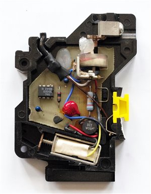
Others with it were ECC but virtually the same design. Only thermal. Both are plug in types called stab-lok and are bakerlite.


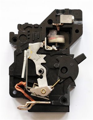
No instantaneous trip mechanism. Only a thermal one.


34200b5e07a12e120f5fc679b8b1b9aa-huge-mcb-with-no-instantanious-trip-mechanism-4.jpg
  • Hi all.


    I received and opened the Federal Electric RCBO I got for a tenner from ebay and have found the same thing. No instantaneous trip

    mechanism.

    Hard to believe on an RCBO.

    This one is actually a 10mA.

    It's the MCB not marked with types that are like this but all the RCBOs I saw on ebay had no type marking.

    It's not that easy to tell from the picture as I had to remove it but there is a centre part so the thermal mechanism would be

    positioned above the electronics, but separated. You can see the fixed part of the contact near the coil.

    The electronics are permanantly fed so it warms up even when switched off and if the RCBO is plugged in first the neutral tail

    becomes live. The trip coil is directly fed by the yellow wire on one side from the L on the load side, so at least if it trips it

    will cut the power to the trip coil. The test button is a link to neutral but there is no switching on that so keeping it pressed in

    after tripping will overhead the test resister. However, I tried this and nothing overloaded; don't know why. Maybe I didn't hold

    it long enough but in theory the length of time I did hold it I expected some noise and wisps of smoke.

    On this one the test button is transparent red and there is an trip LED on the board. Some have non-transparent yellow buttons so

    they probably don't have this LED.

    This is a 30A breaker and the L and N conductors seem a bit small.

    The large neutral tail is misleading as it is connected through a soldered crimp to 2 white conductors for load current and neutral

    link to the circuit board.

    It seems a bit strange that what seems and old bakerlite device with no instantaneous trip mechanism has more modern LED and 2 IC packages on the circuit board.

    b00d42da2407b4089ca5336b52c249aa-original-federal-electric-rcbo-without-instantanious-trip.jpg
  • The "8826" on the IC likely means the chip was manufactured in week 26 of 1988.
  • Thanks for the picture - I remembered the promise of opening it when it arrived. 


    Regarding comments about modern parts and bakelite-type housing: 


    *  US-type RCDs (GFCIs etc) have a long heritage of being electronic, partly because they have tended to demand levels such as 6 mA (based on let-go current) rather than the common European 30 mA (based mainly on hearts). There's (still) debate about whether passive or electronic ones are more reliable in terms of delicate parts to go wrong: this paper (Cohen ~1996?) gives a bit of background mainly from one side of the story. 


     * US breakers appear to like the bakelite "industrial history" look.  Even many modern GFCIs and AFCIs have this look, e.g. these


    We're seeing more and more electronic RCBOs (voltage-dependent for operation) due to the desire to fit into 1 module or to be cheaper. The current-transformer part can be very small if it only feeds an amplifier. 

  • Hard to believe these were manufactured in 1988 without the inclusion of an instantaneous trip mechanism.

    I see what you mean about their liking the bakerlite look. I've seen UK Fed Electric made MCBs to fit in these DBs but made of white plastic. They are totally different internally and therefore narrower. However, if you look at them side on they are padded out to be the same width. They must have made them to allow the continued use of their old DBs.

    Interesting read about electronic verses electromechanical.

    It's still strange that FE stopped making the stablock MCBs with no instantaneous trip and started to make (and mark) them as types 1, 2, 3 & 4 but didn't do the same with the RCBOs.
  • Here's one which was almost certainly installed in 1982. Definitely made in England. It was in a 4-way metal CU which served a garage and outbuildings. Only two ways were used - this was one of the spares. At least the test button worked!

    c18b4398480f43bf62a27ed918918895-original-20200609stablok1.jpg
    3fa5335c020c0f7966979537e6ac8e36-original-20200609stablok2.jpg
    f1f9a494e024b2919bb7937a8f44dadf-original-20200609stablok3.jpg
    5aba04a99214b840630c13e2ebbae905-original-20200609stablok4.jpg
  • Thanks for posting the pics of that. It shows the make up in better detail. I pulled my one apart too quickly.

    I notice that the feed for the board is on the load side on this one instead of the supply side on the one I opened.
  • Thanks for the further pictures. I have never come across such things in the UK - interesting!


    Now, thinking on the comment "without the inclusion of an instantaneous trip mechanism", I start to be curious about whether they do some clever trick like having a deliberately bad balance on the RCD core so that high overcurrents - even though non-residual - cause the RCD part to trip, or some other sensing. I admittedly can't see any other way of sensing in the picture, and can't imagine how a core and wires looking like this could have a reliable level of imbalance. (Sometimes the designers of these things have cunning tricks: for example, a chip commonly used for plug-in RCDs (RV4145) includes a rather neat detection of downstream N-E faults described on p.5, end of first section, which is wanted because these faults in a TN system can make the RCD much less sensitive to L-E faults by creating in effect a short-circuited turn through the core.)  


    Else, perhaps the thermal trip anyway manages to be within the 0.1 s that still persists as the "instantaneous" requirement in IEC standards although all the manufacturers seem to make them so quick that they're even current-limiting (<0.01 s). 


  • Don't think so. The MCBs don't have electronics anyway, so same situation. The one I opened was a 10mA and would think there would be a risk of false tripping if a method like that was used.

    No way the thermal trip manages to be within 0.1. These DBs had to be replaced in an installation because they were taking far too long to trip on a direct fault.

    I think it is as it looks. No instantaneous trip in MCB and RCBO. Hard to understand the thinking of a manufacturer in making these for use in a DB.

  • The RCD part will of course deal with L-E faults, but not a L-N short circuit.


    Let's put the short circuit near to the CU with a loop impedance of 0.2 Ω and so a PSSC of 1150 A - that might heat up the bimetallic strip pretty sharpish. However, at the end of a circuit where the impedance might be 1.0 Ω or more, and if the short circuit has a little more than a negligible impedance, it might cook for long enough to do some damage.


    What did the 15th Edn (or even 14th Edn) require? Surely they must have been compliant!
  • The 15th Edition required equipment to comply with the relevant requirements of the current edition of the applicable British Standard. So if these devices did not comply with BS 3871 or some other appropriate british standard, they ought not to have been used. Appendix 1 of the 15th Edition A1 1983 does not list a BS for RCDs but then BS4293 was not published until 1983. 

    Having looked back at my 15th Edition, how much more simple life was back then!