This discussion has been locked.
You can no longer post new replies to this discussion. If you have a question you can start a new discussion

TT Earthing Systems - Interest by New Zealand

Former Community Member
I am the chair of a Standards NZ committee charged with the production of a technical report to the NZ regulator regarding the possible use of the TT earthing system in NZ.   Currently, NZ uses the MEN earthing system (as does Australia), being similar to the PME earthing system used in the UK but with an earth electrode being required in each electrical installation to assist in keeping the voltage to earth of the neutral conductor of the LV reticulation close to zero.   Otherwise the MEN system is TN-C-S and relies on the PEN conductor as a return path to clear earth faults by the operation of OCPDs.   The use of RCDs is now required for most sub-circuits to provide additional shock protection.  


As is well known, TN systems are not perfect and a broken or high impedance PEN conductor causes the livening of earthed and bonded surfaces, including the chassis of EVs when they are plugged in to EV charging equipment.   It is noted that the IET Wiring Rules do not permit the use of PME systems to supply EV charging equipment unless the voltage on earthed surfaces is held to a non-lethal value.  


Without going into further detail, the committee, in preparing a report, remains concerned about and seeks information on two possible problems.   


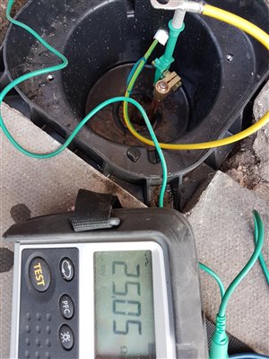
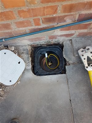
The first is how to attain at reasonable cost a TT earthing electrode system that does not exceed 100 ohms to earth in many NZ locations where the soil resistivity and the seasonal variation of this is high.   Does it cost a fortune to do this in the UK?    We have difficulty at many sites in reducing substation earthing mat and rod systems to less than 10 ohms and sometimes that is not achievable.


The second is how to be reasonably sure that the RCDs in any TT installation will be regularly tested every six months or so by the users of the installation?  RCDs are not perfect but are much more important safety devices when used in a TT installation than in a TN installation.   Therefore regular testing appears to be important to maintain safety.    With non-domestic installations this should not be a problem as their regular testing (by pushbutton) can be linked to annual building inspections or included in maintenance schedules.  However, how does the UK ensure - if it does - that the occupants of domestic TT installations regularly check the operation of their RCDs?   One sensible suggestion made by a committee member was that the regular RCD checking could be linked to the six-monthly call by our Fire and Emergency Service to check the batteries in fire alarms installed in houses.   That might prompt a few people to check their RCDs.    


Since I was intending to ask about the practicability of 100 ohm earth electrode systems in the UK, I thought that I should also enquire about the regular testing of RCDs in domestic installations.  


I should be grateful for any comments or suggestions.


P M R Browne BE(Elect) FIET FENZ

  • Just to show the other side of the coin too, this thread has just prompted me to do a quick Zs test in my TT'd detached garage - which has in the past given me a reading as low as 36Ω from a single 1200mm rod. Today it's still only 42Ω and that's after a very unusual dry spell for this part of the world - the best part of two months with negligible rainfall.


       - Andy.
  • Soil resistivity mapping is available for the UK from the Ordnance Survey.


    That is way way beyond the level of planning used by most electricians, they just look for somewhere no one will trip over the box on top of the rod.


    If you look at YouTube videos of UK electricians installing an earth rod they are usually knocking a 4’ rod in with a 20 oz carpenters claw hammer around the back of a shed, you don’t seem to see them standing on a hop up driving it with a 2lb lump hammer or a small sledgehammer which you generally need to do with a 12’ rod.


    I live on the second terrace River Severn alluvial flood plain, which is actually about the present day flood levels, I can see the river from my bedroom window, but the flood water only gets to the bottom of the road. We are over sand and gravel, which is still quarried just up from us though some of the pits are now flooded as nature reserves and for water sports. Over the sand and gravel is class one horticultural soil, so driving rods actually around where I live is not difficult, but not so far away the bedrock comes to the surface and driving rods is a nonstarter.


    But around here if you have not got a low reading at a depth of 12’ it’s not going to make a huge difference going any further, I put a job up for assessment with a rod reading of over 400 ohms with the rod twelve feet into the ground and the assessor agreed that at that depth it’s a stable reading and unlikely to change.


    You have to bear in mind that here in the UK we are putting a lot of faith in RCD protection rather than getting the earth resistance down in TT installations. Being “old school” I like a 100 mA S-Type RCD main switch upfront of the 30 mA RCDs, but with the change from Type AC to Type A RCDs that is not possible, so the upfront RCD needs to be a 300 mA RCD, which means a lower Ra is required, however 300 mA Type A RCDs are made for the European market so are not readily available rated at more than 63 amps and UK installation practice is to have a 100 amp main switch, so availability of suitable RCDs can be an issue.


    So a lot of installers use a 100 amp main switch and 30 mA RCBOs , which is deemed acceptable. However some use a consumer unit with a 100 amp main switch and a split arrangement with two 30 mA RCDs supplied by internal tails , now bear in mind that we have to use consumer units with steel enclosures in domestic installations, so that is not deemed acceptable. It was something my NAPIT assessor quizzed me on this year as it is a recurring problem he is seeing.


    So personally I see issues with the general standard of TT installations in the UK, many are still protected by voltage operated earth leakage breakers, despite them having been obsolete for over forty years, others have RCDs that do not trip, that have not been tested since the day they were installed and the are some very questionable rod installations.


    Andy Betteridge
  • Actually in the UK 100 ohms is not a 'pass/fail ' limit on a TT system - more a threshold for 'needs investigation'. The immediate fail would be if the resistance was high enough that the exposed voltage on the largest non-tripping fault is below the ELV limit - i.e just under 30mA, for a 30mA RCD, should not result in an electrode voltage rise of more than 50V.  So it could be  about 1500 ohms on a 30ma trip - though in practice  anything anywhere near  that would be very much 'needs urgent  investigation' as probably something has corroded off or been cut. It is however possible to have say 200 ohms in a hot dry summer, and after an inspection of conditions and wiring, to conclude there is no real fault, and it is safe to remain in service.


    Also on a lone transformer feeding one or two farms, it is not that certain that the substation electrode is that great - a regs compliant site could be as high as 20 ohms so long as  the LV and HV earths are separated electrodes.

    In such cases the results of  a multipoint electrode test and a Zs test diverge  as the substation/transformer electrode resistance is in the loop test, but not the mutipoint probe tests. (though the natural variation in repeated tests of the same electrode on various days and with different test electrode positions is probably comparable)

    If the consumer electrode is actually much  lower resistance than the one at the transformer end, then it is not good, as the NE offset voltage  at the transformer (and for all other customers on the same LV branch) moves significantly during a low impedance fault.

    In that case an  installation as a PNB connection may be  more satisfactory - being more like TN-S in terms of where the fault currents flow (even if some folk think of it as a variant of PME)


  • Former Community Member
    0 Former Community Member
    Thank you all again for your informative responses on the construction of practical earth electrode systems.   If you have been able to get your resistance to earth down to 5 ohm with a single long rod, you have done well but you may been fortunate with your soil resistivity at the site.   For what it's worth the earthing rod looks very similar to to these used in NZ and Australia but a single driven rod here can yield a resistance to earth of hundreds of ohms in some places.  The MEN system relies very much on the "multiple" from which its name derives!.    I think that it will be a matter of trial and error involving several driven rods (with good separation among them) to get the connection down to 100 ohms and achieve reliable operation of the 300mA or 100mA property protection RCD.   In some situations, the use of bare wire in trenches or buried electrodes may be necessary.   Canterbury in the South Island has wide areas of old ex-river shingle beds where earthing is particularly difficult.   As has been suggested, the reinforcing in concrete floors may be useful but members of my committee have pointed out that concrete slabs are often insulated by plastic sheeting from the ground against moisture ingress so they may not help much.  


    I am aware there has been pursuit of a reliable broken PEN conductor detector but ideally it should not just give an alarm but operate to interrupt all active conductors as soon as such an event occurs.   That would certainly lessen the risk of livening an EV chassis if that were a concern.   Otherwise the TT system should be effective in preventing it.    However, I can't see wholesale conversion of MEN distribution board sub-circuits here for a while.   Even if the TT earthing system were to be permitted in NZ, it will be some time before our electrical industry here becomes familiar and comfortable with it.   It has been said that many of our electricians don't adequately understand the MEN system as it's the only one permitted and its advantages and disadvantages are not taught to the trade unfortunately - it will take some effort here over some years to have the TT system taught and understood as well.    However, you have to start somewhere! 


    Cheers


    Peter Browne
  • In fact I pulled the basic four foot rod out that can be seen in the picture of the pit and replaced it with three sections of extendable rods, which took the cost of materials up to around sixty pounds. But being twelve feet long the rod has a considerably lower resistance.


    With labour and materials the total cost went up to over hundred pounds, which is far in excess of what generally gets spent. 


    And yes, that is a earth loop impedance tester, the electric supply was on as it was an existing installation that was being upgraded.

    58fb80839cda48d566d1de2032eb1541-original-20180704_170505.jpg
  • If you are lucky a house with a TT installation gets a £ 2.99 earth rod with a clamp to attach the cable and a plastic box to cover it, the whole set up rarely costs a ten pounds in materials.


    This is one of mine from a few years ago for a hot tub.

    0b0bda9f08183e789b320bbd44dc1b01-original-145.jpg


    Here is another one  I did with a decent plastic pit that was then set in concrete.

    36693bfdc0442f390f3dec3243c64f38-original-20180702_172530.jpg


    I do usually allow for enough materials for a reasonable job and take some extendable rods with me so I can pull a four foot rod back out then install a longer one if I cannot get a good test result.


    There was around forty pounds worth of materials for the set up with the pit, which is several times more than is typically spent, the earth rod pit is around thirty pounds.


    Andy Betteridge.
  • mapj1:

    It is a bit sweeping to say that all  TT installations in the UK are poor !


    I actually said "TT installations and their earth rods are rarely installed to a high standard in the UK."


    Which is a factual statement.


    Andy Betteridge
  • The responsibility of maintaining the integrity of the PEN on a public supply should rest squarely with the supply provider. It seems to me that the attitude taken by the supplier is “well here is an earthing terminal, use it if you want”. If you choose not to and employ your own TT arrangement in say an estate that is all PME, there is still a credible risk. So what to do? Nail the supplier for compensation for any injury that might arise! I am sure that they are delighted that the electrical installation industry is picking up the tab for the perceived risk in loss of PEN, especially where EV charging is concerned.
  • In response to the query re our required earth electrode at each installation under our MEN earthing system, AS/NZS 3000 (Australia and NZ Wiring Rules) requires the driving of a single 12mm Dia copper clad rod 1.8 metres into the ground, Other electrodes are allowable but the rod is the most commonly used. There is no requirement to measure its resistance to the general mass of earth. There is a requirement to measure earth loop return impedance but, of course, for a TT-C-S system, the return circuit is via the PEN conductor and is always acceptably low. The driven rod is connected to the earth bar, which has a removable (for testing) link to the neutral bar and helps to hold down the voltage of the PEN conductor and the neutral conductor (also a PEN) of the supplying LV reticulation. Ideally, the reticulation PEN should also be connected to earth rods along its length but for the same purpose but I think this would be rare.

    The problem we had with the proposed (and dropped) requirement for additional electrodes in consumer's installations on PME systems was the resistance to Earth it would need to achieve in order to be effective. For example if we had a 20Ω electrode, a broken PEN that affected just our one installation and the installation had loads connected that attempted to draw say 10A - then we'd have 10V * 20Ω = 200V developed between the installation's earthing system and true Earth - so hardly providing safety. OK you can refine the numbers - with some voltage lost across the electrode, so a reduced voltage appearing across loads, many loads (e.g. those having a fixed resistance) would reduce their current draw somewhat but then there's the possibility of larger loads happening to be connected. If the PEN break was further upstream then you might have a contribution from several consumer's electrodes in parallel, which should help - but on the flipside there would be several consumer's N currents to sink. In the UK even domestic installations can have up to a 100A supply - so to be completely sure of keeping things below the usual limit of 50V we'd have to be looking at ridiculously low values like 0.5Ω for each electrode. So we're interested in how it's approached elsewhere - or whether it's just a case of PEN conductors being more reliable where they're not built from rotting Edwardian paper & lead cables or corroding 1970s aluminium ones like much of ours seems to be.

     
    By the way, there are devices in the process of patent approval that deal with the loss of neutral issue for EV application and they don’t require an electrode.

    BS 7671 allows a couple of different 'voltage monitoring' approaches - some use a local electrode (or an artificial N star point for 3-phase systems) as a reference, but others (as mentioned) just monitor the L-N voltage. That second approach as a number of disadvantages - not least where supplied from a 3-phase distribution system that it's entirely possible for the L-N voltage to remain within limits (e.g. 230V+10%-6%) but the N-Earth voltage to greatly exceed 50V (or indeed 70V) - depending on the relative loading of the three phases. It also can't disconnect promptly without risking a lot of nuisance tripping since the L-N (or L-PE) voltage can be taken out of limits by "normal" faults elsewhere in the installation, distribution system or other installations, which can take anything up to 5s to clear (sometimes longer for some faults on the distribution system). Thus it's only really intended where there are no other practical alternatives - thus BS 7671 doesn't permit that approach in 3-phase installations where an artificial N point would provide a more reliable reference.


       - Andy.
  • It is a bit sweeping to say that all  TT installations in the UK are poor !

    I think it depends where you live and the general experience of the local 'sparks'. In areas with a lot of TT folk are more used to it. For example round here (Hants) there are plenty of stables where the stock is so valuable that anything less  than an absolutely 1st class installation is not even considered. This sort of sets the bar quite high for all electricians who have seen it, even when they are only doing  the more down market "value engineered"  jobs where a detached garage or caravan point on the side of a garden summer house is being set up as a TT island supplied from a PME house.

    Equally from the no. of times it comes up on this forum, there are clearly parts of the country where there is almost no TT experience at all, and on first encounters  folk get easily confused by it - I suspect that some very clear guidance will be needed for the first times this is introduced in a new country as is proposed here.


    In that case an NZ version of this sort of http://IET wiring Matters tutorial example  may be worth considering, although it could be improved by adding further clarifications  about how to achieve electrical separation from the house services, and the desirability of plastic pipes for outside taps near charge points and so on.  Even a length of a meter or so of plastic pipe in a metal section  is a very significant fault current limiter.


    Another article here


    (isolation of water pipes unofficially demonstrated  here  - the actual tests from about half way in)