This discussion is locked.
You cannot post a reply to this discussion. If you have a question start a new discussion

Zs, to test or calculate?

A large contractor working on our site have told me yesterday that it is their policy not to live test final circuits where they cannot use a plug? In order to reduce risk, they will now only calculate Zs, on circuits where they would have to open an enclosure, such as FCU's and light fittings.
The control measures we insist are in place, are IP2X equipment, GS38 leads, two man rule with second man having resus training, among others. So I feel the risk has been reduced to as low as reasonably practicable. An d my instinct tells me that a measured Zs reading must be more accurate than a calculated one, since it will include all parallel paths under test.
The contractor is happy to live test distribution circuits, so it seems they want to pick and choose.
They also state that this is how things are now, and have worked at many different sites, Cross Rail, Heathrow, various MOD sites etc, and that they al accept this as common practice.

I like some opinions to find out what's going on out there on other sites. 
Parents
  • That's true (lyledunn).  A method that compares voltage magnitudes with and without a resistive load (where that load impedance is many times the source impedance, e.g. to take 20 A) is very insensitive to reactance in the source - it practically doesn't see it at all. 


    One can make inferences based on curve fitting for a range of resistive loads, but that's more for amusement than practical ... I've tried it a few times. 


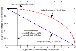
    The following plot was my attempt some years ago to illustrate the relation between current and voltage when a varied resistive load (conductance increasing from open-circuit to short-circuit) is connected to a source with either purely resistive (blue) or purely reactive (red) impedance, or to a current-limited power-electronic source.

    - With the resistive source and load the gradient is a nice straight line as with dc circuits, so any measurement that varies the load between (say) zero and 20 A in a system with 1 kA short-circuit current would make a good estimate of the short-circuit current. 

    - But with the reactive source and resistive load the estimate based on this same pair of currents would be a much higher short circuit current than the actual value that's been chosen here to be the same as in the resistive case, because the voltage drop due to mainly resistive current flowing through the reactive source impedance is pretty well in quadrature with the larger source voltage, just as you say. 

    - (And on the other hand, the current-limited inverter could regulate its voltage to look very stiff, and yet provide much lower short-circuit current: it is 'brittle' stiffness!)

    fd25a70f5dda7bc808aecf8919fccae9-original-vi.png


    "In theory", using phasor calculation, one could calculate the source impedance easily for a Thevenin-style source with resistive and/or reactive impedance. But that would require knowing the angle relation between the voltage phasors at the source (assumed constant for the 0 A and 20 A case) and at the measurement point. The simple practical measurements don't have a way to know this, and just measure voltage magnitude. It is possible with analog methods (phase-locked loop) or digital methods (extrapolate a sine-wave for further cycles) to keep a memory of the phase of the source-voltage based on the times when the current isn't being drawn, and to assume this value continues in the few cycles afterwards when the test-current is being drawn. Then one should be able to get a better calculation, although the small change in voltage for a resistive perturbation of a reactive system would still make it more susceptible to noise. Using a test-inductor (or capacitor) as the load instead of a resistor would let the source reactance be measured while largely ignoring the source resistance. Or electronics could synthesise the currents in phase and quadrature. 

    Getting away from phasors, one can take rapid pulses of current such that much of the voltage drop is caused by L*di/dt instead of R*i, as a way to assess inductance (but this is rather dependent on local shunt capacitance). 


    There's a lot that can be done. Some has been in other applications of impedance estimation, such as inverters that use reactive power consumption to avoid excessive voltage rise with active power injection, or distance-relays that look at the L*di/dt rather than phasors.  Installation testers have got cleverer and more digital, but I'm not sure about the current state of art in implementations by the usual manufacturers of today's products.  They tend not to say anything very interesting about the fine details!  One has to test the tester.  


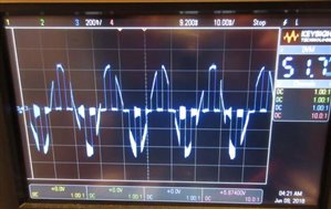
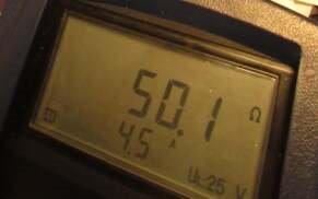
    I don't remember the details of the setup, but the following are from a quick check a few years ago, using an oscilloscope to see what a simple MFT was doing during (I think) a low-current (RCD-friendly) loop test.  It correctly measured the oscilloscope's supposed input resistance, and the oscilloscope showed an interesting waveform that definitely wasn't sinusoidal. 
    593e6f29ddf3a90425f51a19538b83da-original-zest_osc.jpg  35759f8b710f1e4602108c025a5d9f43-original-zest_result.jpg


Reply
  • That's true (lyledunn).  A method that compares voltage magnitudes with and without a resistive load (where that load impedance is many times the source impedance, e.g. to take 20 A) is very insensitive to reactance in the source - it practically doesn't see it at all. 


    One can make inferences based on curve fitting for a range of resistive loads, but that's more for amusement than practical ... I've tried it a few times. 


    The following plot was my attempt some years ago to illustrate the relation between current and voltage when a varied resistive load (conductance increasing from open-circuit to short-circuit) is connected to a source with either purely resistive (blue) or purely reactive (red) impedance, or to a current-limited power-electronic source.

    - With the resistive source and load the gradient is a nice straight line as with dc circuits, so any measurement that varies the load between (say) zero and 20 A in a system with 1 kA short-circuit current would make a good estimate of the short-circuit current. 

    - But with the reactive source and resistive load the estimate based on this same pair of currents would be a much higher short circuit current than the actual value that's been chosen here to be the same as in the resistive case, because the voltage drop due to mainly resistive current flowing through the reactive source impedance is pretty well in quadrature with the larger source voltage, just as you say. 

    - (And on the other hand, the current-limited inverter could regulate its voltage to look very stiff, and yet provide much lower short-circuit current: it is 'brittle' stiffness!)

    fd25a70f5dda7bc808aecf8919fccae9-original-vi.png


    "In theory", using phasor calculation, one could calculate the source impedance easily for a Thevenin-style source with resistive and/or reactive impedance. But that would require knowing the angle relation between the voltage phasors at the source (assumed constant for the 0 A and 20 A case) and at the measurement point. The simple practical measurements don't have a way to know this, and just measure voltage magnitude. It is possible with analog methods (phase-locked loop) or digital methods (extrapolate a sine-wave for further cycles) to keep a memory of the phase of the source-voltage based on the times when the current isn't being drawn, and to assume this value continues in the few cycles afterwards when the test-current is being drawn. Then one should be able to get a better calculation, although the small change in voltage for a resistive perturbation of a reactive system would still make it more susceptible to noise. Using a test-inductor (or capacitor) as the load instead of a resistor would let the source reactance be measured while largely ignoring the source resistance. Or electronics could synthesise the currents in phase and quadrature. 

    Getting away from phasors, one can take rapid pulses of current such that much of the voltage drop is caused by L*di/dt instead of R*i, as a way to assess inductance (but this is rather dependent on local shunt capacitance). 


    There's a lot that can be done. Some has been in other applications of impedance estimation, such as inverters that use reactive power consumption to avoid excessive voltage rise with active power injection, or distance-relays that look at the L*di/dt rather than phasors.  Installation testers have got cleverer and more digital, but I'm not sure about the current state of art in implementations by the usual manufacturers of today's products.  They tend not to say anything very interesting about the fine details!  One has to test the tester.  


    I don't remember the details of the setup, but the following are from a quick check a few years ago, using an oscilloscope to see what a simple MFT was doing during (I think) a low-current (RCD-friendly) loop test.  It correctly measured the oscilloscope's supposed input resistance, and the oscilloscope showed an interesting waveform that definitely wasn't sinusoidal. 
    593e6f29ddf3a90425f51a19538b83da-original-zest_osc.jpg  35759f8b710f1e4602108c025a5d9f43-original-zest_result.jpg


Children
No Data