This discussion has been locked.
You can no longer post new replies to this discussion. If you have a question you can start a new discussion

EMI suppressor and protective earth

I would be most grateful if the boffins in here could explain something please.


This suppressor was fitted to my lathe on the load side of the VSD. Something went wrong when I was parting off the other day - the tool dug in and the motor stalled - and now it is running roughly. Back to square 1!


In an attempt to determine whether the VSD has been damaged, I tried connecting another motor, but I was unable to demonstrate protective earth continuity. The cable from the green terminal on the suppressor goes to the motor's earth terminal. I expected that the case of the suppressor would be the supply side of the PE, but apparently not. So with the suppressor fitted there is no PE to the motor, which I find a little disconcerting.


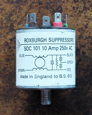
FWIW, the capacitance between red and black is about 0.5 µF, the resistance is 470 kΩ, and the capacitance between each of red and black to green is 9 nF.


Would somebody kindly explain whether this is safe please?

83550124b8831caa7e200218ed497ebc-huge-20200629suppressor.jpg
Parents
  • You have done the right thing. Without that CPC you would be creating a flying earth island and  as Graham alludes that is common inside a class 2 enclosure, but is quite dangerous for a metal bodied item as the two capacitors will float the case voltage to somewhere mid supply, not an issue inside a plastic box, less clever in a case like this.  Also where is the ADS if the motor faults to the case..

    The aim of the caps is to make all 3 cores L/N/E equipotential to fast edged signals. (though still 230V between them at 50Hz and lower)


    If you ever do have RFI problems, you may wish to RF choke the CPC, to raise the impedance to signals much higher than 50Hz. The usual then is a ferrite ring or beads
Reply
  • You have done the right thing. Without that CPC you would be creating a flying earth island and  as Graham alludes that is common inside a class 2 enclosure, but is quite dangerous for a metal bodied item as the two capacitors will float the case voltage to somewhere mid supply, not an issue inside a plastic box, less clever in a case like this.  Also where is the ADS if the motor faults to the case..

    The aim of the caps is to make all 3 cores L/N/E equipotential to fast edged signals. (though still 230V between them at 50Hz and lower)


    If you ever do have RFI problems, you may wish to RF choke the CPC, to raise the impedance to signals much higher than 50Hz. The usual then is a ferrite ring or beads
Children
No Data