This discussion is locked.
You cannot post a reply to this discussion. If you have a question start a new discussion

Earth rod resistance

Hi

Hoping someone can point me in the right direction!

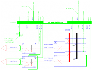
On site we are trying to review our existing distribution earthing arrangements.  We have 11kV or 6.6kV distributed to local substations where we drop to 415v locally.  We generally have PNB systems with common HV equipment and LV neutral earth arrangements.  Typical one shown below
ebe497219bf639b0954936dc05b950cf-huge-substation-earthing-arrangements.png

I have reviewed several 'local authority' documents which suggest a maximum of 20ohms for earth rod resistance, but looking through BS EN 7430 it suggests on a similar arrangement in A.2 a maximum of 1 ohms?  Could anyone kindly advise what it should be? or point me in the right direction?

Many thanks

Al
Parents
  • Former Community Member
    0 Former Community Member
    With a combined HV and LV electrode, you need to calculating the resistance needed to limit the rise of earth potential, and the relative step and touch potentials  - although a collective 1 Ohm isn't an unreasonable starting point - this is the collective resistance of the HV (or steelwork) and LV electrode, not just the rod banged in the ground


    I would also check conductors E202 and E205 - it looks like you have both the transformer neutral earth and the switchboard neutral earth in place - which is a bit unusual. I would expect to see just E205 connected to the electrode (if you have REF functions on DB 02 incoming circuit breakers)


    Regards


    OMS
Reply
  • Former Community Member
    0 Former Community Member
    With a combined HV and LV electrode, you need to calculating the resistance needed to limit the rise of earth potential, and the relative step and touch potentials  - although a collective 1 Ohm isn't an unreasonable starting point - this is the collective resistance of the HV (or steelwork) and LV electrode, not just the rod banged in the ground


    I would also check conductors E202 and E205 - it looks like you have both the transformer neutral earth and the switchboard neutral earth in place - which is a bit unusual. I would expect to see just E205 connected to the electrode (if you have REF functions on DB 02 incoming circuit breakers)


    Regards


    OMS
Children
No Data