This discussion is locked.
You cannot post a reply to this discussion. If you have a question start a new discussion

Earth rod resistance

Hi

Hoping someone can point me in the right direction!

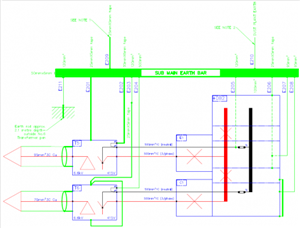
On site we are trying to review our existing distribution earthing arrangements.  We have 11kV or 6.6kV distributed to local substations where we drop to 415v locally.  We generally have PNB systems with common HV equipment and LV neutral earth arrangements.  Typical one shown below
ebe497219bf639b0954936dc05b950cf-huge-substation-earthing-arrangements.png

I have reviewed several 'local authority' documents which suggest a maximum of 20ohms for earth rod resistance, but looking through BS EN 7430 it suggests on a similar arrangement in A.2 a maximum of 1 ohms?  Could anyone kindly advise what it should be? or point me in the right direction?

Many thanks

Al
Parents
  • The 20 ohm figure is sometimes seen as the limit for the LV earth electrodes, when HV side (transformer core and box) and LV side (neutral star point) earths are well separated - such a site could be "hot" in the sense that during an HV to transformer case fault, the rise of voltage may be quite a bit more than the LV network would reasonably tolerate during the short time while the HV side ADS operates.  This tends to be the case for rural pole pig transfomers supplying a few farms, not your situation. The HV earth is a wire running down the pole with the transfomer on it, the LV earth is the wire running down from the neutral line at the next pole along, or an equivalent.

    The 20 ohm figure  appears in some of the distribution code guidance for DNOs.


    The one ohm figure is about right for a 'cold' site, where HV side and LV side earthing are inter-connected or very close, and  for a moderate HV side prospective fault current.

    However, if you are on a 33kV line, or the 11kV line is short and fat for some reason, so the prospective fault current into terra-firma while the HV side disconnects is higher than a few hundred amps, then less than an ohm may well be needed, or in some cases more may be OK - it is only a guide.

    Note that underground HV feeds that bring their own earthed armour also need treating a bit differently, as the prospective fault current is then quite a bit higher.
Reply
  • The 20 ohm figure is sometimes seen as the limit for the LV earth electrodes, when HV side (transformer core and box) and LV side (neutral star point) earths are well separated - such a site could be "hot" in the sense that during an HV to transformer case fault, the rise of voltage may be quite a bit more than the LV network would reasonably tolerate during the short time while the HV side ADS operates.  This tends to be the case for rural pole pig transfomers supplying a few farms, not your situation. The HV earth is a wire running down the pole with the transfomer on it, the LV earth is the wire running down from the neutral line at the next pole along, or an equivalent.

    The 20 ohm figure  appears in some of the distribution code guidance for DNOs.


    The one ohm figure is about right for a 'cold' site, where HV side and LV side earthing are inter-connected or very close, and  for a moderate HV side prospective fault current.

    However, if you are on a 33kV line, or the 11kV line is short and fat for some reason, so the prospective fault current into terra-firma while the HV side disconnects is higher than a few hundred amps, then less than an ohm may well be needed, or in some cases more may be OK - it is only a guide.

    Note that underground HV feeds that bring their own earthed armour also need treating a bit differently, as the prospective fault current is then quite a bit higher.
Children
No Data