This discussion is locked.
You cannot post a reply to this discussion. If you have a question start a new discussion

Modular wiring home run cable sizing

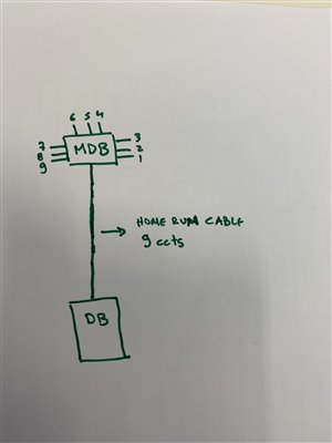
Hello, I am trying to confirm the appropriate cable size for a home run cable in a modular wiring system. There is a 9-port MDB that supplies  radial circuits with socket outlets. As per BS7671, the appropriate grouping factor to be applied is either 0.5 (table 4C1) or 0.45 (table 4B5) assuming all circuits are carrying more than 30% of the current capacity of the home run cable. This ends up in having to use 6mm2 or even 10mm2 cables instead of 4mm2 that would be expected for radial circuits in 20A MCBs.


What are your thoughts?


Any comments would be appreciated.


Having said that and looking at regulation 2.3.3.1 from appendix 4 I have the feeling that based on the BS even when we are supplying lighting and power circuits in trunking, we would have to oversize all circuits to comply with the grouping factors. So how is it justified when we are installing a power and lighting DB with all these outgoing circuits in different sizes and loads in 2.5 (or even 1.5) for lighting and 4 for power?
  • If you look at note 1 at the bottom of the table 4C1 - it says - these factors are applicable to uniform groups of cables - EQUALLY LOADED. 


    This means that if you have a shower circuit grouped for part of its run (Usually near the DB)  together with 2 lighting and 2 socket circuits and a couple of other circuits - none of these circuits are equally loaded and likely to be working at full load producing full heat in every cable at the same time. Generally I believe you can disregard grouping factors in a simple case like this. This is a design decision and depends on what is there. (I've always seen this as a bit of allowance for cable temperature diversity. - they produce heat at different times and at different rates)


    If you had 10 lighting circuits - or even better 10 large motors - all grouped together and likely to be all running at the same time with similar loadings then you'd definitely have to apply grouping factors or find a way to keep the cabling separate from each other.
  • Another way to look at it, is that the total load cannot be more than the supply, and I expect that your MCBs add up to more than the available supply. Thus the cables cannot all be fully loaded, and each can be allocated a percentage of loading, which will probably give a grouping factor close to 1. Anyway as Tatty says, there is nothing to worry about. I notice you are using 4mm² cables at 20A, is this due to thermal insulation, because if not you already have significant derating.


    Regards

    David
  • So is there nine final circuits each supplying a solitary double socket or are there several sockets on each final circuit?


    Andy B
  • Thanks for your comments.

    The issue is that I not sure how to justify a group factor close to 1. The 4mm2 ccc is 32 A for ref method B (assuming the home run as conduit) and each circuit should normally be drawing around 5-6A. But as these are general sockets, should I not take under consideration that 20A could be drawn? This would mean that the ccc of the cable would be 20/0.5=40A and I would have to go with 6mm2 (41A @ ref Method B). Each circuit is supplying 5-6 double sockets.
  • This isn’t inspiring me at the moment.


    Are you familiar with the kitchen appliance circuits that were popular twenty years ago in new build houses and flats which comprised a B32 MCB with a 6.0 mm twin and earth cable to a multi-gang grid switch supplying each appliance in the kitchen through a single socket or fused connection unit connected with 1.5 or 2.5 mm twin and earth cable? The final runs to each appliance are protected from overload by limiting what is supplied, I inspected and tested one last week.


    As far as I can see with the arrangement you are proposing you probably need the equivalent of nine big cables running through the box and conduit, all the way to the socket fittings I’m not seeing the advantage of having the box.


    Sketch it out on a piece of paper and take a photo to post, perhaps it will make more sense.


     Andy B.
  • 4cb87d55a6ddbf3384fb37ed8eaff4cc-original-image.jpg
  • The question is about the home run cables from the DB to the master distribution box. After the MDB I dont think there is an issue with 4mm2. 


    I am trying to show that 4mm2 should be fine for the home run cable. just not sure about the details of the proper calculation that should be considered
  • Chris 223:
    4cb87d55a6ddbf3384fb37ed8eaff4cc-original-image.jpg


    If there are not nine circuit protective devices in the MDB to protect the nine final circuits you are looking at wiring everything in 4.0 mm and having a 32 amp protective device upfront of everything in the distribution board.


     Unless the MDB has nine circuits in and nine out with nine MCBs in the upfront distribution board.


    Andy B.


  • Former Community Member
    0 Former Community Member
    Sparkingchip:

     Unless the MDB has nine circuits in and nine out with nine MCBs in the upfront distribution board.


    Andy B.


    It's a modular system - it's exactly that, Andy


    Regards


    OMS


  • The question is the same, what is the supply overall rating going to be? If 60A you have only 2 circuits spread over 9 cables, use the value 1. Even if 100A the value of 1 is very safe, that is only 11A average per circuit with 4mm cables.