
lyledunn:
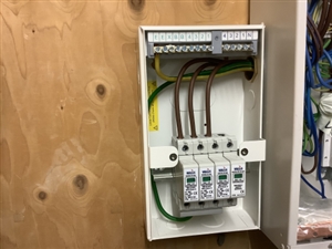
The above follows manufacturers instructions. Am I right in assuming that the neutral module is not used as protection is afforded by the N/E bond on a TN-C-S system?
There are only 2 types of connection in BS 7671 for three-phase systems with Neutral - CT1 (Fig 534.3 in BS 7671) and CT2 (Fig 534.4 in BS 7671).
What is shown in your picture appears to be neither of those, if the system has a Neutral ... but yes you are correct, in this case if the N and PE are bonded close to the SPD the N-PE for CT1 may not be necessary.
In TN-C-S systems, because the Neutral separates from PE downstream of the service head, especially in premises with LPS, there may well be impulses between N and PE by the time you get to the distribution board / switchboard. It may therefore be OK to use this at the main switchboard / distribution board, but Type 2 or Type 3 SPDs downstream would need all 4 SPDs.
I still think connection of the N-PE SPD would be the best approach (since it's been provided), as shown in Fig 543.3 and Fig 16A5 in BS 7671 - but the OSG says refer to manufacturer's instructions !
lyledunn:
Exactly Graham. However, both CT1 and CT2 are presented as an “example” of such connection arrangements. That implies that there is more than one way to comply.
Apologies for that, I typed a response which really didn't say what I wanted to say to be honest, and edited it afterwards. The original response began the same way.
We're about to take you to the IET registration website. Don't worry though, you'll be sent straight back to the community after completing the registration.
Continue to the IET registration site


