This discussion has been locked.
You can no longer post new replies to this discussion. If you have a question you can start a new discussion

Existing TNCS site with Fixed Generator Adding Circuits

Former Community Member
Sorry for the length of this.


I am adding some lights and sockets to existing circuits in a SP board. And providing bonding to metal oil pipes coming into this workshop from underground.

They have a diesel SP generator supplying (installed in the last 5 years)  ‘essential’ SP Dis boards across the site feeding lights and basic power - in case of supply interruptions.

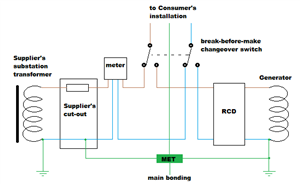
It seems that the existing TP boards had SP circuits removed and diverted into these newer SP boards - so some metal cable management systems are shared between the standard TP circuits and those fed via the change over SP boards. The SP boards are being supplied by a 3 position change change over switch. The positions are: Mains on, all off, generator on. The idea is that the three position switch is thrown to manually, isolating street supply and switching over to the generator which is then also manually started.


There was no data left at all about the system design, or generator.  Okay i can go back to the manufacturer and obtain info about the generator..  But where can i find more about the regs governing SP generators and their integration into fixed TNCS systems please?


These 3 position switches also isolate and switch over the earths. This also means isolation from local bonds to the building and the oil pipes.  For now i have instructed the client not to use the switches nor the generator.


My concern here is that in all areas there is always a TP Dis boards supplying TP and SP non essential circuits in the area. Isolating the earth in this way seems dangerous, especially as all the bonds are on the TP boards. We are also in a reasonably high lightning area, so if earth was isolated this could also impact any surge protection - not that there is any installed yet .


I have yet to check, but assuming the Generator is both staked at source (i have seen a think earth wire go into the ground), and that it is also deliberately or fortuitously linked back to the MET in the mains distribution shed.


I think the action need to be taken here is: 


Link out the earth connection in the Triple pole changeovers so earth is not switched.  Provide additional warning that it should not be remove, inside and outside the box.

Ensure continuity of earth between Mains and Generator back to the earth stake at the Generator, this will mean though that i have an Earth stake at the Generator position that is also connected to a TNCS system.

With the generator running, assuming all other circuit related tests have been completed and recorded:

Check Prospective fault current and ZS to ensure the protective devices still comply.

Provide adequate signage in relation to bonds between the two earth systems as well as notes about dual supply and isolation.


Really looking for some guidance here please.


Thanks


john


  • If the earthing is switched it needs to be ganged so that it cannot be interrupted when L or N are in use.

    Usually with a bit of cunning, just  switching L and N is enough and earthing is left permanently attached (!)  It is not wise to have "earthing " that may or may not be connected to other 'earthing' that is simultaneously accessible, as there may be a voltage between two metal objects that you could be straddling. There may be a good reason to switch the CPCs, but  the normal arrangement is to have a common earth if at all possible.


    If the genset supply is to be run when the street supply cable may be severed, you cannot rely on the company earth alone, but there is no reason not to have your own electrode (s) in parallel with the MET all the time.

    There should be a single solid N-E bond inside or near to the genset, in such a way that the neutral switching means it is NOT in circuit when the external mains is in use - the DNO also provide an N-E bond, and there really should only be one NE bond in use at a time.

    I suspect there will be more,  but does this make sense with what has been done first ?

    Mike.


  • Former Community Member
    0 Former Community Member
    Hi yes makes sense to bring to one system, thank you.  But. I cannot see how we maintain a single N-E link in use at all times.


    I need to check, but i assume there is another isolator at the Generator set that also needs to be operated.  But...


    Use cases where both N-E links could be in circuit simultaneously: -

    1) If they loose the phase that the SP board is fed on, then they could choose to run the Genset and keep the TP boards running, supplying the circuits on the two running phases.

    2) running up the generator and conducting routine testing while the street supply is healthy

    3) Total failure of all three phases, then resumption of street power while genset is running 


    What issues could arise if both N-E links were kept in place for the scenarios above?


    Thanks


    John

  • In effect the CPC that links the two NE bonds is in  parallel with the neutral, and could end up carrying a significant fraction of the load  current that should flow in the neutral.

    In reality so long as the earthing is robust enough for the possible current, and the situations are exceptional rather than the rule, it is not likely to be an issue - far more dangerous would be if there was some state with no NE bond at the genset, so the whole lot was not really referenced to earth.

    There is the small matter of it being illegal to combine N and E currents in one conductor under the ESCQR in the UK as well, unless you are a DNO, but in lots of places around the world, and some in the UK, it happens without too much upset.

    This drawing by another forum contributor from a post a while back shows an example method for how it can be done with no issues.

    Obviously the neutrals (and lives) from anything not on the genset changeover will be left connected to the main supply, but that is not an issue - you would never see shared neutrals between circuits anyway, would you ?


    Edited to link to AJJs image - which I thought I had, having found it by google, and recalling the original discussion was about a chap with a Lister genset. I was a but surprised it was on photobucket, but hey ho it must have been 'lifted'. Apologies Andy.

  • But. I cannot see how we maintain a single N-E link in use at all times.

    :

    Use cases where both N-E links could be in circuit simultaneously: -

    1) If they loose the phase that the SP board is fed on, then they could choose to run the Genset and keep the TP boards running, supplying the circuits on the two running phases.

    2) running up the generator and conducting routine testing while the street supply is healthy

    3) Total failure of all three phases, then resumption of street power while genset is running

    To (hopefully) clarify - the requirement to have only a single N-PE link only applies to each independent system - where you have two distinct systems (i.e. where there are no connections between the live (either line or neutral) conductors of the two systems then you can (and indeed must have) an N-PE link in each system. The earthing/bonding arrangements can be shared of course.


    In all the above cases the change-over switch should ensure that the generator supplied circuits are kept separated from the grid-supplied circuits - so you have two distinct systems, even if they're both running at the same time.


       - Andy.
  • Oh, and hopefully a slightly clearer (less photobucket watermarked Frowning2) version of that diagram:

    08e9fb371606bf7fbc50fa2e6aa1a87f-original-generatordetailtn-c-s_zps660b2d3f.png


    (as hinted above, unless the generator is quite substantial it may well not be able to provide enough current under fault conditions to operate overcurrent protective devices for ADS  (Zs readings can't always be trusted on that score either) - so RCD(s)s may be required.

       - Andy.
  • Former Community Member
    0 Former Community Member
    Yes, this is how i imagined it should be.  I just need to check the distribution and main bonding conductor, layout and size.


    Thank you.


    John
  • Former Community Member
    0 Former Community Member
    I have not done any digging or boiler plate checking, but it is about the size of 12kva system I have seen on the net - so you wouldn't want it in your eye...


    Thanks all.


    John
  • AJJewsbury:

    Oh, and hopefully a slightly clearer (less photobucket watermarked Frowning2) version of that diagram:

    ....

       - Andy.


    Apologies, I recalled the diagram, but not the creator from a discussion about a Lister unit, and so I googled for IET forum Lister genest changeover, and got the photobucket one. It must have been lifted by a 3rd party if that was not you.

    If the forum search was better I might have been able to find the original...

    Mike.


  • No apologies needed Mike. I'm happy if it's proving useful. I presumed the watermark was one of photobucket's attempts to persuade people to use their premium service after they blocked images from free accounts being used on public sites.

      - Andy.