The IET is carrying out some important updates between 17-30 April and all of our websites will be view only. For more information, read this Announcement

This discussion is locked.
You cannot post a reply to this discussion. If you have a question start a new discussion

Safety Isolating Transformers

Former Community Member
I am an electrical inspector and I have come to large a newly installed machine (multiple moving parts, multiple independent motors and safety circuits) where the supply for the device is on a safety isolating transformer. This means that when I try and test the earth loop impedence for the supply I get no connection. In my mind this means that there is the potential that in an earth fault situation the device might not trip its breakers and other circuit protective devices as no fault path is generated. I have never seen an entire device protected by a safety isolating transformer and I don't know enough about them to say so I thought I would come to the experts on here for assistance! What would the advantages of this be and would there be safety implications of an installation like this?


Thanks in advance


Tom
  • No expert. Depends on the application. It may be a situation where you want a circuit that is floating, not grounded. Say an environment with varying ground resistance and for blocking noise or ground loops. There should be overcurrent protection that will work, there maybe thermal cut out on the TX , likely there are overloads on the motors. But this is a supplied machine as a whole in-service and working, perhaps installed by the manufacturer? There will be instructions of use for safe usage, or is this something in a Lab environment?  Are you fixed wire Inspecting or Machine Inspecting?
  • Well it is an IT system -  and the advantage is that touching either live pole cannot give you a shock to ground, so a single fault live to case need not require the system to be shut down, and a double fault (both lives to case)  will simply cut the power.

    The domestic example is the UK bathroom shaver socket.

    It is not so good in a distributed system, where one piece of equipment may go live to case on pole 1, and another on pole 2, if you then pick up both pieces of equipment.

    However,  if combined with a CPC and  earth fault detection, it allow the first fault to be detected, but the system to keep running to reach a condition where it is safe to stop. This is commonly used  in situations where a dead stop might be more dangerous than keeping going.  (medical equipment, London Underground, The magnetic cranes in scrapyards,  and the wiring on some ships come to mind as examples)

    In the dark ages the fault detection might have been as simple as two lamps wired between the live poles with the centre tap earthed. When all is well, both are dim. When one side is accidentally earthed one light is bright and the other goes out, but the power can be kept on. Nowadays considerably more sophisticated equipment performs a similar function.

    Mike
  • Former Community Member
    0 Former Community Member
    Thanks for the replies, Its actually an amusement ride so I've got the main supply to the panel is on an isolating transformer and power is fed out of the panel to three phase connections on the track to a number of cars. If I had an earth fault on a supply to the track or one of the motors running the cars would that trip out the MPCBs that are protecting those circuits? All the earth connections are good and the main earth bar in the panel is linked to the rest of the buildings earth circuit.


    The manufacturer has supplied the supply transformer so they are anticipating it but I've never seen an entire ride supplied by an isolating transformer?
  • If I had an earth fault on a supply to the track or one of the motors running the cars would that trip out the MPCBs that are protecting those circuits?

    No, it should not do, as in an IT system, a grounded phase is not dangerous, all the phase to phase voltages for motors etc remain unchanged in this state.

    What the controller should do is include something to alert the operator to the fault, allowing the ride to be brought to  a halt in controlled way with the power still on, and one phase grounded.

    Mike.
  • Former Community Member
    0 Former Community Member
    I've now had a chance to sit and read my schematics with a coffee and there is current monitoring but it seems to turn the ride off in the event that there is an earth fault so I'm not sure what benefit they are getting from having this as an IT system?


    Would a ride guest be protected from shock in the event that a motor shorted to the chassis and a person touched the chassis/ track and the motor?


    Thanks for all the assistance, every day is a school day!
  • I'm not sure what benefit they are getting from having this as an IT system?

    I guess an IT (or separated) system has a number of advatanges - e.g. it's passively safe - i.e. it remains safe on first fault even if disconnection doesn't happen for some reason. If it's a bit like a giant scalextric set then loop impedances in general and specifically earthing of the cars might be a bit unreliable (e.g. dirt/oxide on the track/pickups) - or if the disconnection relay contact weld. Or perhaps the disconnection time wants to be longer than consistent with shock protection - e.g.to ride through transient overloads or leakage that would otherwise nuisance trip. 


    It'll likely also give some protection against direct contact with one pole (when conventional ADS wouldn't helo anyway) if say the track is exposed (but not against simultaneous contact with both poles of course).


    The transformer might also do a little voltage conversion if the setup is from abroad or intended for export.


       - Andy.
  • Former Community Member
    0 Former Community Member
    Thanks all for the assistance. I think I've got everything I need now and I now know a lot more about isolating transformers!


    Till next time


    Tom
  • Sounds like a 740 location to me.
  • Former Community Member
    0 Former Community Member
    Sorry to drag this up again but I was hoping you guys may be able to give me some more assistance!


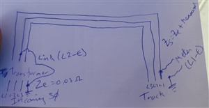
    So I have now done a lot more research into these systems and read some more standards, I believe that as per the standard I have to test the earth loop of my final circuit according to my sketch (apologies for how terrible and hand drawn it is......) but when I do I get no connection. Would I have to do this live and if so how do I do this safely? Is there specific equipment for measuring the earth loop on IT systems?

    b4572bb5774b3440d271809a4f4b0ef4-original-whatsapp-image-2021-03-23-at-13.55.35.jpg


    Thanks in advance!


    Tom
  • tommatwalker:

    Sorry to drag this up again but I was hoping you guys may be able to give me some more assistance!


    So I have now done a lot more research into these systems and read some more standards, I believe that as per the standard I have to test the earth loop of my final circuit according to my sketch (apologies for how terrible and hand drawn it is......) but when I do I get no connection. Would I have to do this live and if so how do I do this safely? Is there specific equipment for measuring the earth loop on IT systems?

    b4572bb5774b3440d271809a4f4b0ef4-original-whatsapp-image-2021-03-23-at-13.55.35.jpg


    Thanks in advance!


    Tom


    You may like to look at Fig 9C, Appendix 9, of B.S. 7671 page 491. It illustrates the IT system.


    Z.


1 2