This is related to my previous question :
https://communities.theiet.org/discussions/viewtopic/1037/28277
In the case of a medical facility which has only group 1 medical locations, such as different types of examination rooms, massage rooms, hydrotherapy rooms, physiotherapy rooms, etc.
Let's say we have 10 such locations on the ground floor.
All circuits are feeded from the main panel located on the ground floor.
Q1:
I cannot picture the whole bonding system architecture.
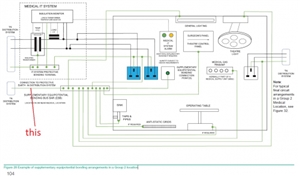
The EBBs in all these 10 location, should they be connected to the MEB (main earthing bar of the MEB) by means of a separate bonding conductor? I mean the conductor which is framed in red in the attached image (it is Figure 28 from HTM 06-01 - please ignore the elements which are specific to group 2 medical locations, in this topic we are talking about group 1 medical locations).
Or the EBBs don't need a separate connection to the MEB because they create a local equipotential "point" and they are anyhow connected through the cpc of all circuits ?
Q2:
If the answer of Q1 is "Yes, they should be connected to the MEB by separate bonding conductor", then could this be considered a main bonding conductor? How should be its CSA determined?
Q3:
If the local EBBs should be connected to the MEB, should they be connected individually or collectively (radial or loop) ?
Please point to the regulations / guidance / documents where i can find a diagram or some explanation.
Thank you.