This discussion is locked.
You cannot post a reply to this discussion. If you have a question start a new discussion

The Graphs in Fig 3A4-6. What does the vertical part of the characteristic mean?

There is a problem with these graphs. What is it and how should it be corrected?
  • Graham, I do not understand what you mean. Circuit breakers and fuses give curves for 0.1 to 10,000 seconds. Time to trip or fuse under various "overcurrent" conditions can be very useful, particularly for mechanical loads on motors. BS7671 applies in all installation areas, it may not present data for higher current installations, but has all the principles and regulations for all sizes of jobs. It is true I consider the circuit breaker data on the graph grossly misleading, and it has obviously misled Andy, but manufacturers data can also have the same defect. I wonder if you think that operating a fuse at greater than its "fusing" current is in some way incorrect, the continuous rating of a circuit may be very different from short term conditions, for example for motors starting with a high inertial load, or large incandescent lamps or heating elements.
  • davezawadi (David Stone):

    Graham, I do not understand what you mean. Circuit breakers and fuses give curves for 0.1 to 10,000 seconds. Time to trip or fuse under various "overcurrent" conditions can be very useful, particularly for mechanical loads on motors. BS7671 applies in all installation areas, it may not present data for higher current installations, but has all the principles and regulations for all sizes of jobs. It is true I consider the circuit breaker data on the graph grossly misleading, and it has obviously misled Andy, but manufacturers data can also have the same defect. I wonder if you think that operating a fuse at greater than its "fusing" current is in some way incorrect, the continuous rating of a circuit may be very different from short term conditions, for example for motors starting with a high inertial load, or large incandescent lamps or heating elements.


    The graphs in BS 7671 are only the RHS of the "area" described by the range of real fuses (or circuit breakers) that come off a production line. So, whilst they are useful for some things, they are not useful for others, such as selectivity, or determining whether a "keen" fuse towards the LHS of the range will operate due to a motor starting under load. Compare the time/current characteristics of fuses shown in BS 1362, which show the whole area for 3 A and 13 A fuses:
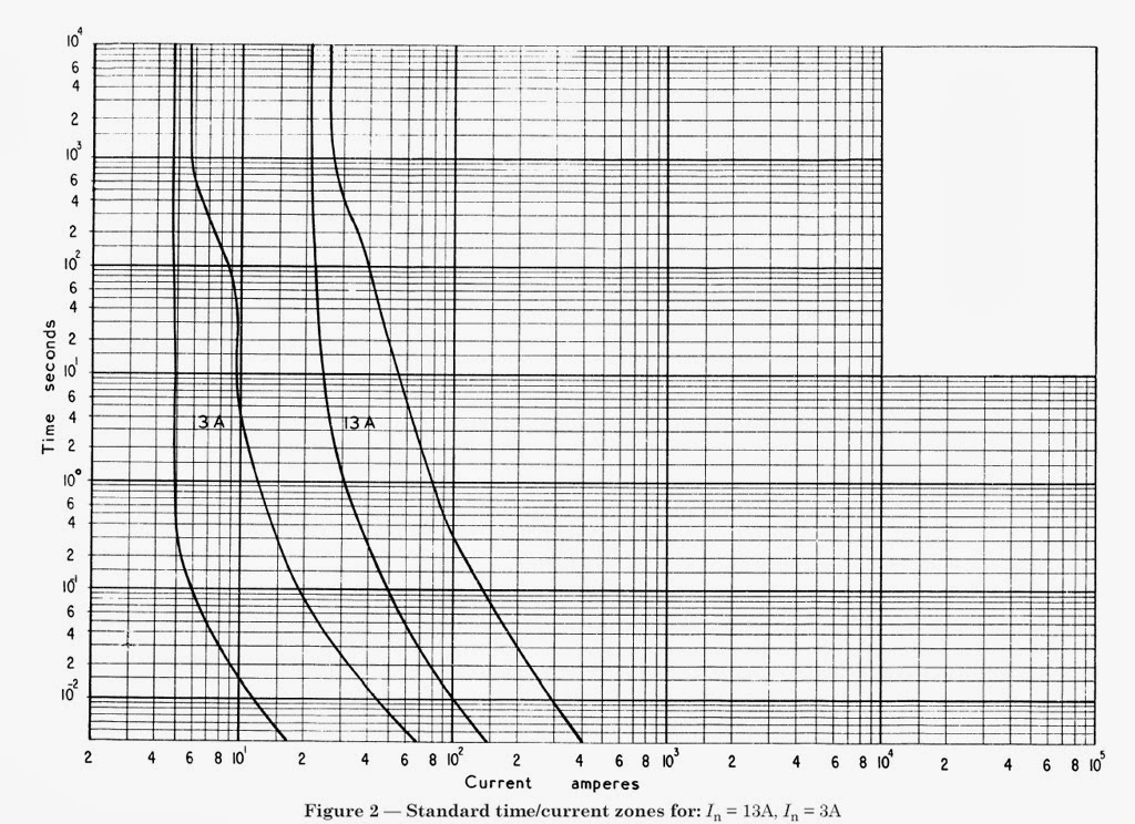

    Linked from https://pat-testing-fss.blogspot.com/2014/02/whay-13-amp-fuse-does-not-seem-to-blow.html
  • They are certainly peculiar graphs.


    Normally one would find the desired prospective current along the abscissa, go up to the line, and then turn left to find the trip time at the ordinate. As stated above, if one is in the magnetic trip area, it does not really work.


    However, one might wish to be assured that a PFC (at the end of a final circuit) is sufficient to operate ADS within the correct interval, in which case go the other way and the graphs may be more useful.


    Odd that they do not have a range of values as with the ones supplied by manufacturers.
  • It makes sense to have a logarithmic rather than linear scale where you want to be able to read off values reasonably accurately at different scales, accommodated on a single graph. For example sometimes we are interested in slight overloads that trip in the order of 1000s. If time was on a linear scale of 0-1000, that graph would be useless for reading of values that occur in in 10s or less for example.
  • That is true if you want to put many devices on one graph.  However, you still have the difficulty of reading a value to contend with.  My point is that if we want to actually use this data maybe a graph of this sort is not the best way.  Simply providing data for each device for the five points given plus simply equation to obtain intermediate values might be better.


    t = t1 + ( (t2 - t1) * ((I2 - I1) / (I2 - I1)) ) I think that is right but I am converting from a different form so check it before use.


    Regards 


    Geoff Blackwell
  • I did NOT suggest putting time on a linear scale, just a useful one. The BS1361 fuses have a particularly wide range Graham, because they are not really there for overload protection, just short circuit protection (or severe fault). Because of the range, one can see why this might be.

    Graphs with straight lines or proper accurate equations and matching scaling are more useful. Looking at fuses, the adiabatic current ratings of fuses are set by the physics Mike outlined. They should not have huge ranges, just reasonable manufacturing tolerances. If one wishes to see the entire envelope, fair enough, but we wish in most cases to examine the worst-case time/current value. Quicker fusing is not a problem for faults to overloads, it is the longest time that is dangerous. Next time I have a spare few minutes I will attempt to produce an equation and axis scaling which produces straight lines.

    Geoff, you do have an error but it is interesting (I2 - I1) / (I2 - I1) always equals 1! I think you were attempting linear interpolation, between 2 points, but this is not it. I will leave the correct answer to the student!


  • David


    t = t1 + ( (t2 - t1) * ((I2 - I1) / (I2 - I1)) )  should have been t = t1 + ( (t2 - t1) * ((Ix - I1) / (I2 - I1)) ) 


    The error is that I put I2 where it should have been Ix.  The result is now the same as my application produces.  This application also graphs all of the equations and by inspection the given result is probably correct.


    Putting the values in for the 315A fuse


    t = t1 + ( (t2 - t1) * ((Ix - I1) / (I2 - I1)) ) 


    5 + (( 1 - 5) * ((2500 - 2000)/(3050 - 2000)) )


    5 + ( (-4)*((500)/(1050)) ) = 3.1 seconds as required


    t1 = 5 sec

    t2 = 1 sec

    I2 = 3050A (current that gives 1 sec)

    I1 = 2000A (current that gives 5 sec)

    Ix = 2500A (current used for my example)


    IMO for most practical engineering use this is as accurate as it needs to be.  Cables only come in a limited number of sizes!


    Regards

    Geoff Blackwell
  • You are not the student Geoff. 10/10!!


    You are correct of course about cable sizes, but I would like to change those graphs. I think your result is at least as accurate as we need, and we could also make the MCB graphs rather better without the "instant trip" vertical by adding the calculation from the let-through energy and available PSCC. I will write something down.


    Regards

    David