This discussion is locked.
You cannot post a reply to this discussion. If you have a question start a new discussion

NICEIC consumer unit labels

Former Community Member
Hi


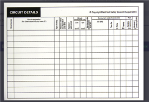
I am looking to add some labels similar to the NICEC one bellow prior to my Napit assessment and I am unsure what value is expected in the box for maximum disconnect time.

Does any one know if it should be Circuit breaker disconnect time, *1 or *5 time for the RCD?


Also for the box for type of wiring I assume they are looking for T+E, SGL, SWA etc.


Thanks


Alan

e10908bbd9a85a18e8332f923bd71c16-huge-image.png

Parents
  • Hello Alan


    When you say you're looking to add some labels - I assume - from the picture you have posted -  you mean you're going to put a Schedule of circuit details stuck somewhere near to the DB or perhaps in the front lid?


    Maximum disconnection times See 411.3.2  and typically see table 41.1 page 59 for Final Circuits disconnection times.

    Look along the top of the table and you will see 120V<Uo<230 - this means you use the values below this for Live to Earth values of (in theory) less than or equal to 230V.

    This bit includes 400V systems as the live to earth value of a three phase system is still less than or equal to 230V in theory. So on a TN System (AC electrics) the maximum disconnection time is 0.4 and on a TT system the maximum disconnection time is 0.2 seconds  


    411.3.2.3 and 411.3.2.4 gives you disconnection times for a distribution circuit - typically the circuit supplying a DB for example.


    I'm unsure how that form you have pasted can be copy right as it seems to be a fairly standard generic sheet of basic information. All that asks for is what size of RCD are you using on a given circuit. 


    When you come to a test form and it askes for the RCD test results, the value you input depends on what the RCD is doing.

    If the RCD is there for Fault protection (All RCDs greater than 30mA, (Usually) but in a TT system the 30mA RCDs are often there for fault protection too (in a typical household installation)

    I'd input the X 1 test result, for all of the RCDs greater than 30mA as theres no need to do a x 5 test for those and for the 30mA RCDs where its also there for both fault and additional protection, then use the x 5 figure in the test sheet results box.

    If the RCD is there for solely for additional protection only, I'd use the x 5 figure for the test sheet.
Reply
  • Hello Alan


    When you say you're looking to add some labels - I assume - from the picture you have posted -  you mean you're going to put a Schedule of circuit details stuck somewhere near to the DB or perhaps in the front lid?


    Maximum disconnection times See 411.3.2  and typically see table 41.1 page 59 for Final Circuits disconnection times.

    Look along the top of the table and you will see 120V<Uo<230 - this means you use the values below this for Live to Earth values of (in theory) less than or equal to 230V.

    This bit includes 400V systems as the live to earth value of a three phase system is still less than or equal to 230V in theory. So on a TN System (AC electrics) the maximum disconnection time is 0.4 and on a TT system the maximum disconnection time is 0.2 seconds  


    411.3.2.3 and 411.3.2.4 gives you disconnection times for a distribution circuit - typically the circuit supplying a DB for example.


    I'm unsure how that form you have pasted can be copy right as it seems to be a fairly standard generic sheet of basic information. All that asks for is what size of RCD are you using on a given circuit. 


    When you come to a test form and it askes for the RCD test results, the value you input depends on what the RCD is doing.

    If the RCD is there for Fault protection (All RCDs greater than 30mA, (Usually) but in a TT system the 30mA RCDs are often there for fault protection too (in a typical household installation)

    I'd input the X 1 test result, for all of the RCDs greater than 30mA as theres no need to do a x 5 test for those and for the 30mA RCDs where its also there for both fault and additional protection, then use the x 5 figure in the test sheet results box.

    If the RCD is there for solely for additional protection only, I'd use the x 5 figure for the test sheet.
Children
No Data