This discussion is locked.
You cannot post a reply to this discussion. If you have a question start a new discussion

Calculating maximum Za for Time Delay RCDs

Hi All,


Has anyone any experience calculating time delay maximum earth electrode resistance for time delayed RCDs, im looking at Table 3A in Appendix 3 but cant quite my head around it.


Standard 500ma would get 100ohms Ra. 


(50v / 500ma) x 1000 = 100RA

4557a7ce2499a05c386ab10a81e7c400-huge-image.png

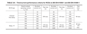
The manufactuer used has setting for the 500ma time delay for 0.15s, 0.25s, 0.5s, 1s, 2.5s and 5s. I cant quite work out how that relates to the attached table.


Are the 0.15s and 0.25s faster than non delay? Id assume not, as its a delay


Some worked examples for the 500ma would be very helpful, im trying to discriminate with a downstream 300ma standard RCCB.


Thanks!
Parents
  • The RA x IΔn≤50V requirement is based soley on the rated residual current - so the time delay doesn't come into it. So calculate just as you normally would.


    That bit really only makes sure that leakage currents (rather than a hard L-PE fault) can't raise the earthing system to a hazardous voltages (due to likely high earth impedances with TT systems) without anything tripping eventually. There's a separate requirement to ensure disconnection within a given time for normal ADS requirement (which would involve making sure that Zs is low enough to trip the RCD within the required time, based on Uo, taking delays into consideration) - but it's unusal for that to be more onerous than the 50V limit above.


    Table 3A (lower part) is for S-type i.e. "selective" RCDs - non-adjustables ones that should discriminate with downstream instantaneous RCDs. Adjustable RCDs are different and you'd have to use numbers based on the setting rather than anything in table 3A.


       - Andy.
Reply
  • The RA x IΔn≤50V requirement is based soley on the rated residual current - so the time delay doesn't come into it. So calculate just as you normally would.


    That bit really only makes sure that leakage currents (rather than a hard L-PE fault) can't raise the earthing system to a hazardous voltages (due to likely high earth impedances with TT systems) without anything tripping eventually. There's a separate requirement to ensure disconnection within a given time for normal ADS requirement (which would involve making sure that Zs is low enough to trip the RCD within the required time, based on Uo, taking delays into consideration) - but it's unusal for that to be more onerous than the 50V limit above.


    Table 3A (lower part) is for S-type i.e. "selective" RCDs - non-adjustables ones that should discriminate with downstream instantaneous RCDs. Adjustable RCDs are different and you'd have to use numbers based on the setting rather than anything in table 3A.


       - Andy.
Children
No Data