This discussion is locked.
You cannot post a reply to this discussion. If you have a question start a new discussion

J.W. Fan Dismantling.

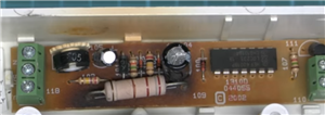
At about 4mins+ in J.W. advocates connecting the fan motor directly to the mains supply if needed. Surely this can not be correct. What is the big Volt dropper resistor for? I don't think that the motor is 240 Volt rated.


Comments please.

Extractor Fan Timer Teardown - Bing video


Z.
Parents
  • That resistor (109) (that is a bit undersized and running hot), is only creating a PELV supply for the  HEF4001 CMOS chip (thing with the 14 legs) that is some NOR gates strung up to make a monostable, time constant set by the variable resistor and C105

    220 odd of the 230 are dropped, and a diode and a capacitor (104) plus a zener create a low current regulated DC for the timer.

    The timer is triggered by the 270k resistor whose number is obscured from the switched live bringing in just under a mA to kick things off.

    When the timer is on the 1k5 resistor (107) puts a few mA into the gate of the triac (111) This gives the fan the mains voltage minus no more than a volt or so when its gate is stimulated.

    1d7c258ae9279caa5562d9f730c376ab-original-fan-timer.png
Reply
  • That resistor (109) (that is a bit undersized and running hot), is only creating a PELV supply for the  HEF4001 CMOS chip (thing with the 14 legs) that is some NOR gates strung up to make a monostable, time constant set by the variable resistor and C105

    220 odd of the 230 are dropped, and a diode and a capacitor (104) plus a zener create a low current regulated DC for the timer.

    The timer is triggered by the 270k resistor whose number is obscured from the switched live bringing in just under a mA to kick things off.

    When the timer is on the 1k5 resistor (107) puts a few mA into the gate of the triac (111) This gives the fan the mains voltage minus no more than a volt or so when its gate is stimulated.

    1d7c258ae9279caa5562d9f730c376ab-original-fan-timer.png
Children
No Data