This discussion is locked.
You cannot post a reply to this discussion. If you have a question start a new discussion

Appendix 4, section 6.1 equation 6

Former Community Member


85b1fc637cfb5e3825ed2b73d8b54527-original-image.png

Hi I am working through equation 6 for an ambient temperature of 50 degrees for 1mm 90degC thermoplastic cable (Table 4E2A)

11d17c7d56aee28e7d23803363b44f10-original-image.png

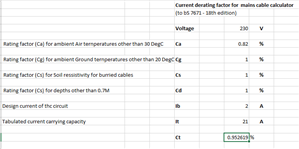
I get a correction factor of 0.95 for a 2A load. 

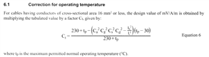
Do i divide the mV/A/m by this factor ? 

The text says multiply, but that would mean the resistance decreases with the increase in temperature (or have I got the sum wrong?)

Parents
  • That is a formula to conjure with, though I do not think I ever have done so in that form …

    We can check it by asking what do we expect, well we know that the resistance of the copper rises with temperature, & the voltage  drop in millivolts per amp is just milliohms by another name.  

    So,  if we changed  the Cg, Cs Cd etc are in the direction that they are less than one when the conditions are worse - hotter, then the formulation also needs to be the way up that reflects a higher resistance when for example ambient is hotter.

    The 230 and 30 figures are just rather clunky ways of fitting a line to the not very fast changing plot of copper resistance versus temperature. (you will often see it published as +0.39 % to + 0.4%   per degree C, for temperatures around 20C-50C so a 30 degree rise is about a 11% -12% increase in resistance.)

    If you really are running a mere 2A through a 20A cable, you can probably drop most of the formula into the sea and just consider the effect of the higher ambient temperature, as the self heating part will be very small.

    It should come out dashed close to the fully-calculated answer.

    regards mike.


Reply
  • That is a formula to conjure with, though I do not think I ever have done so in that form …

    We can check it by asking what do we expect, well we know that the resistance of the copper rises with temperature, & the voltage  drop in millivolts per amp is just milliohms by another name.  

    So,  if we changed  the Cg, Cs Cd etc are in the direction that they are less than one when the conditions are worse - hotter, then the formulation also needs to be the way up that reflects a higher resistance when for example ambient is hotter.

    The 230 and 30 figures are just rather clunky ways of fitting a line to the not very fast changing plot of copper resistance versus temperature. (you will often see it published as +0.39 % to + 0.4%   per degree C, for temperatures around 20C-50C so a 30 degree rise is about a 11% -12% increase in resistance.)

    If you really are running a mere 2A through a 20A cable, you can probably drop most of the formula into the sea and just consider the effect of the higher ambient temperature, as the self heating part will be very small.

    It should come out dashed close to the fully-calculated answer.

    regards mike.


Children
No Data