This discussion has been locked.
You can no longer post new replies to this discussion. If you have a question you can start a new discussion

Appendix 4, section 6.1 equation 6

Former Community Member


85b1fc637cfb5e3825ed2b73d8b54527-original-image.png

Hi I am working through equation 6 for an ambient temperature of 50 degrees for 1mm 90degC thermoplastic cable (Table 4E2A)
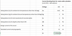
11d17c7d56aee28e7d23803363b44f10-original-image.png

I get a correction factor of 0.95 for a 2A load. 

Do i divide the mV/A/m by this factor ? 

The text says multiply, but that would mean the resistance decreases with the increase in temperature (or have I got the sum wrong?)

  • I'd just round up the 0.952619 to 1.0 and call it a day. We ain't that precise in the real world of chucking in cables and “power” electrics.

    Please read the last paragraph on page 381.

    Also, please read the NOTE in 6.1 regarding the APPROXIMATE  resistance temperature coefficient. The calculation is very approximate.

    Quite so. As something of a collector of rules of thumb, I'm inclined to agree.  Often we seem to calculate by computer, measure with micrometer, mark in chalk, cut with an axe…

    There is another way to check, the rule of 16, which is even more approximate. Namely that a single core 1mm cross -section and is 16 milliohms per metre at room temp (more like 19 when running hot) so if you had 300m each way in  2.5mm2, you may expect 3.8 ohms or so cold rising to more like 4.2 ohms when hot.  So turning the question around, Is an 8 volt drop at full load going to stop the party?

    Mike.

  • I think the intention was to use 1mm2 Mike as indicated in OP.

  • Former Community Member
    0 Former Community Member

    Thanks Lyedunn, that the bit I didn't understand, multiplying by 0.95 gives and advantage in the hotter environment, i would have expected a greater volt drop due to the increased resistance

  • Former Community Member
    0 Former Community Member

    Thanks Mike,  you two approximations there are both around the 11-12% increase for the effect of temperature, however my 0.95 factor is only half that, from the rules of thumb I would have expected a value closer to 0.88 so it looks like the self-heating of the cable is reducing the effect of the correction factor for ambient in my sum. 

    In you first post you say “if we changed  the Cg, Cs Cd etc are in the direction that they are less than one”  - I just took the Ca straight from the table at 0.82 I (assumed this to be a multiplier. Is this actually the % by which the capacity drops?) 

    I.e should I have flipped that value  (1/0.82) to 122% ? If do the sum then works out to 0.89% which is closer to the expected value

    This discussion has been great for me, it not about the numerical accuracy of the answer, but understand the principles it is based upon

  • Sorry -I was a bit quick with the typing when I wrote that, its not the clearest.

    Yes these are not percentage changes, but absolute multipliers /dividers, depending  what you are calculating and you need to keep your wits about you.

    The book value for  voltage drop assumes fully loaded, so 30C ambient and 70C in the copper core or r 90C for some cables. 

    Here your ambient is raised, but you will see less than the 40C rise, a lot less than a 40C rise actually (that is the thing with squared currents are really powers - I squared R and all that) The assumption is that temp rise is linearly proportional to power dissipated in the cable, so all the correction factors that are linear scaling factors for current consumption become squared for heating and power loss..

    mike

  • Thanks Andy, my questioning was over the wording of the application of factor to  the mA/V/M figure  - multiplying it by 0.95 make it smaller, dividing by 0.95 makes it larger

    Yes, you're under-running the cable, so the conductor is cooler than usual, so has a lower resistance, so a reduced voltage drop.

    (or have I missed the point again?)

       - Andy.

  • The biggest point here is that the spreadsheet you have made is simply incorrect and you should fix it. Those are not percentages for factors, and at some point, you will get the whole lot VERY muddled if you carry on like this. The various rating factors are decimal fractions of unity, if you want to use percentages the tabulated numbers must be multiplied by 100 so 0.82 becomes 82%. I would stay away from percentages if I were you because they are the least understood “simple” mathematical concept in the world. Even our dear Government and the BBC don't realise that a percentage change of a small number is still a small number, 382% increase of 10 is only 38.2, but of course, it sounds huge to make an impact, particularly if it is Covid deaths! Because of the low current in your cable, the temperature rise will be essentially zero. The rise is not linear with increasing current, because the cable resistance also increases with temperature. In your case, low current, high ambient temperature, almost all the change is due to the ambient number, very little by self-heating.


    David CEng 

  • Note 1 to Table 4E2A tells you to derate the cable to 70 degrees unless the terminals can handle  90 degrees, the cable won’t be running at full temp, but to be technically correct the cable needs to be treated as 70 degree cable.

    As it’s a temporary installation HO7RNF cable is probably the correct cable to use, which takes you to one of the 4F tables, but no one would generally expect someone to make a 300 metre long “extension lead” with 1.0 mm conductors, so you won’t find entries for 1.00 mm cable as it’s pretty flimsy.

    You have not not said what the actual load is, an appliance or lighting or what period you are defining as “temporary“. 

    I might be considering 2.5 mm H07RN-F  as a fairly robust cable for a temporary supply that can be reused. 


  • H07RN-F is available with 1.5 mm conductors, but not generally considered suitable for temporary electrical distribution systems.

    https://www.elandcables.com/cables/h07rn-f-bs-en-50525-2-21-flexible-rubber-cable

  • Former Community Member
    0 Former Community Member

    Thanks Everyone, if I can just summarise all of the answers:

    Ct should be =((230+50)- (0.82^2-(2^2/21^2)) * (50-30))/(230+50)  = 0.952

    Ct is multiplied by the mV/A/M value in this instance decreasing its value and decreasing the volt drop.

    This is because the load on the cable is less than maximum (under running the cable) and decreasing its value.  So for this cable running at 21A with the 0.82 multiplier the CT would actually be 1.0234 at 50 degrees (increasing the mV/A/M value (but only just).

    Running at 2A the 0.82 multiplier is “decreased”  to 0.95 (closer to 1) because there is less self-heating in the cable, decreasing the mV/A/M value (but only just).

    So all in all the specified mV/A/M is at max current and max conductor temp, ambient temp has very little effect and cable and can almost be ignored. 

    So a 90Cable could still be run at max current in an 80 degree ambient albeit with a increase in voltage drop