This discussion is locked.
You cannot post a reply to this discussion. If you have a question start a new discussion

Regulation for rewring back box?

Former Community Member

Hi, I'm currently holding an MEng in EEE, but not a certified electrician otherwise. 

I want to install smart light switches in my “dwelling”. I have encountered issues where the current back box is standard 74x74x25, but I would need extend it to 86x86x38 for the new light switch. 

I want check do I need part P certificate, or planning permission? How to be compliant while minimise the cost? (I have no experience in dwelling electrical work)

PS: The dwelling is a new build (2019) 
PPS: I might consider obtain required certificate(s) myself if is not too expensive. Since I like do these kind of work, so it might be cost effective in the long term. 

  • You need to know how to wire a light switch, it does not tell you how to do it in the Wiring Regulations or any of the guides to the regs such as the OSG or similar.

    You need an electrical installation book, I’m not sure what the best one is these days and they won’t answer this particular question.

  • Now I am getting a bit worried.

    There are no neutrals in those diagrams.

    What you have is T&E used as switched lines, which is why they have brown sleeving. Three way (or four plus) involves crossover switches.

    Happy to help you, but I think that there comes a time when you need to get the assistance of a competent sparks.

    So far, nothing seems to be notifiable.

    I might add that there is more than one way to wire two-way lighting.

  • Former Community Member
    0 Former Community Member

    Thank you both for caring about my health and safety so much. Really appreciate it. So far, I still find this matter is under my comfort zoom.

    -----

    I have a degree in EEE, so it's not hard for me to understand the theory side of things. And combine information from different sources.

    Thanks to @mapj1, I have read all the wiring information from the Flameport website, include how muti-way switches are normally wired. www.flameport.com/.../lighting_circuits_diagrams.cs4

    The part that I'm concerned about is compliance and practical convention. I want to avoid making unstandardized wiring/hack and leaving the fellow electrician wondering what is going on and risk their safety.

    I will of course not touch any of the wirings until I'm sure how they work and what I need to do.

    -----

    To address the concern, below are my current understanding and thought process:

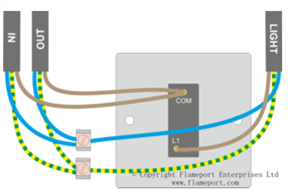
    I understand the image from flameport website does not have a real natural wire. And in the post above, the natural wire is "borrowed" as an output of the switch, which is actually live.

    The picture of the back box I posted is a 1-way switch, with a loop at the switch. So the two of the incoming T&E wire are from the source and to the next switch (with their live connected to common), and the other wire is connected to the light bulb. All the natural and earth wires are connected, which confirms that no borrow exist. (Like the image below)

    97b9593e01bfd7e3fc16381cb4c51245-original-image.png


    What I'm trying to say in the previous post is two fold. 
    The first fold is given the figure as it is, would it be legal to convert it to one-way by abanded the wires in the latter two back box?
    The second fold is if I have access to the neutral wire, which I need to check tomorrow. Then can I also safely terminate it in the first back box.
    And for both termination/abandon what marking do I need?

    I will of course come to it tomorrow with the actual wiring in my home, to be more certain of the setup I need to work with.

  • Former Community Member
    0 Former Community Member

    Chris Pearson: 

    What you have is T&E used as switched lines, which is why they have brown sleeving. Three way (or four plus) involves crossover switches.

    I think my previous post says my reasoning for thinking the T&E wiring is not used as a switched line. (no borrow). Please correct me if I'm wrong.


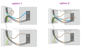
    I might add that there is more than one way to wire two-way lighting.

    Yes, I'm currently aware of two ways,

    f0e57af319a4e2206f5cc539bd3d7ea9-original-image.png
  • The Wiring Regulations is not a book that tells you how to wire an installation, there is little practical guidance in it apart from a couple of schematics of how to lay out socket circuits in the appendixes.

    It sets out requirements without actually telling you to how comply or actually do things.


  • Chris Pearson: 

    What you have is T&E used as switched lines, which is why they have brown sleeving. Three way (or four plus) involves crossover switches.

    benforone:

    I think my previous post says my reasoning for thinking the T&E wiring is not used as a switched line. (no borrow). Please correct me if I'm wrong.

    The brown in the T&E at the top is an unswitched line - it comes either from a ceiling rose or junction box. The blue oversleeved in brown is the switched line - that goes  back to the ceiling rose or JB where it is connected to the line of the luminaire. In those diagrams, there is no neutral at any of the switches except the loop-at-the-switch diagram.

    ETA: you appear to have loop-at-the-switch in the example which you show. You would have your two unswitched lines in common, the switched line in L1. Then you need to add a wee bit of blue cable from the neutral block to your smart switch, assuming that it is mains-powered. All the CPCs remain connected to each other and the switch if it is Class I.

    As for abandoning the 2-way cables, I'd keep them rather than chop them off. Ideally all the conductors should be earthed at the supply end.

  • The most useful thing you can do for the next electrician in is leave an envelope of photos and or wiring drawings near the consumer unit. This almost never happens, but knowing where the joints are and how things are wired really saves a lot of time. 

    Do not worry about the notification part. 

    Putting the full weight of the regs to one side for a minute, the level of testing that is really required for a safe light switch swap you can probably do with careful use of a cheap multi-meter or even a battery and buzzer set, as with a bit of thought it can all be done ‘dead’ - i.e. with the power off.  ‘proper’ electricians test sets have fused tips on the probes,  and can measure very high and very low resistances very accurately, and have a price that reflects this. 

    But this is a light switch swap,  not the rewire of a hospital… You may however still need a long ‘wander lead’ and a tame accomplice.

    It is useful to either write on the cable (sharpie pens) or use coloured tapes to be sure which wire is which - putting the switch straight across the supply instead of in series with the lamps is a dramatic and confidence reducing  event.

    spare cables should be insulated and folded back out the way rather than cut short unless there is a good reason - you may need to revert at some point. (it is good practice to earth unused cables, but not essential to safe operation)

    Mike.


  • Bear in mind there could be more than one circuit at both switches and lighting points.

    I got caught out at a light fitting, I could see it from the consumer unit, so turned the lamp on then turned the breakers off to find the one that disconnected the supply to the lamp by watching the lamp extinguish.

    Then I got up to start work and got a shock, because there was another circuit looped through the ceiling rose to the one that the switched live for the lamp came from.

    Assume everything has been wired by an idiot just to be on the safe side and there may be multiple supplies at light fittings from different circuits, as well as at switches where they are to be expected.

    As you have a modern installation it’s unlikely there’s borrowed neutrals interconnecting circuits, but again don’t assume that is so and actually check the neutrals have not got voltage on them as you disconnect things.

    As said above it’s good practice to maintain the circuit protective conductor and earth the unused live conductors both line and neutral. 


  • Sparkingchip: 
    Bear in mind there could be more than one circuit at both switches and lighting points.

    Yes, it doesn't seem unreasonable to have the two way switch at the bottom of the stairs for the landing light fed from the upstairs lighting circuit, and the switch at the top for the hall light fed from the downstairs one. So that's two switches, each with two circuits.

    Another heffalump trap would be having the landing lights fed from the downstairs circuit.