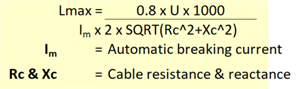
I have both TNS and IT system and While sizing the cables, Can I use the below equation for both the TNS and IT systems, in arriving at the maximum cable length for the end of fault current.
For small cables, you can forget the reactance term. There is however a potential problem with IT systems used for personal protection (for example operating theatres etc) and that is very long cables potentially present a capacitance to Earth risk from contact with a conductor and an Earth. This needs to be a lot of cable to be realistic in practice, but the designer needs to be aware of it. The voltage drop is your cable design criterion, with the Earth loop impedance usually a limitation before volt drop steps in but would not apply to IT systems. Allowable volt drop is fairly flexible, as is the consideration of maximum versus likely loading. The design job is not necessarily simple! Why the question might have an interesting answer, or are you a student?
Odd formula - are R and X per unit length, or the full value for the length under consderation.
Also the factor of 1k is a bit odd. What are the other units ?
This is of the right form but you need to keep your wits about you - I presume that Im relates to instant breaking and already includes the edge of tolerance ,so for example your ‘Im’ for a 10 amp B-type MCB might be 5 times the nominal rating, 50 amps.
Is U the supply voltage, after allowing for the voltage drop of the supply side upstream of the cable in question ? A PME supply may manage ⅓ of an ohm of Zdb, but an IT system may not depending how it is derived. You may need to add in the effect of impedances outside the building, as these are still in the fault loop.
And do you need instant trip, or is fault protection provided elsewhere ? You may be fine with a higher fault impendance.
I have both TNS and IT system and While sizing the cables, Can I use the below equation for both the TNS and IT systems, in arriving at the maximum cable length for the end of fault current.
Looks like this formula is only for voltage drop. There are other factors such as thermal effects (adiabatic) and meeting the relevant disconnection times for protection against electric shock which may shorten the maximum length.
In this formula, looks like Rc and Xc are provided in ohms per km or milliohms per metre (not a problem, just pointing this out).
Looks like you are using a voltage factor Cmin of 0.8 at the utilisation (far) end of the cable, which assumes a maximum voltage drop of 20 % - assuming U is the nominal voltage (the peak being U x Cmax) it exceeds the usual limits of product standards, and IEC and CENELEC standard voltages … but that may well be OK for your application but not in general.
Instead of Im, BS 7671 would probably use In (nominal rating of the device) or Ib (design current) if this is lower than Im.
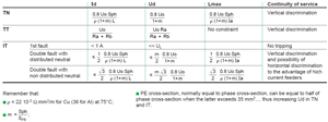
Not wanting to restrict the discussion to the UK (where PEN conductors are largely unused in private installations), I also don't believe the formula is valid for single phase circuits where the metallic sheath or armour of a cable is used as a PEN conductor.
Since the equation is to determine the fault current at the end of line (before the downstream circuit breaker); In other words, minimum short circuit current (at the end of line) is used to verify whether the circuit breaker can be tripped for the magnitude of short circuit current at the end of line.
I have a question that, Why no source impedance has been included in the below equation from the Schneider cahier technique? If the source impedance is included, it would further reduce the short circuit current. So, I think source impedance to be included in the equation to determine the end of fault current.
Since the equation is to determine the fault current at the end of line (before the downstream circuit breaker); In other words, minimum short circuit current (at the end of line) is used to verify whether the circuit breaker can be tripped for the magnitude of short circuit current at the end of line.
you're correct … the formula you are quoting ignores the external earth fault loop impedance Ze or Zdb (or that calculated for L-L or L-N fault with the prospective short circuit current), which in effect makes it a volt-drop formula for a voltage drop of 20 % as I said, if you use Ib or In
In BS 7671 for the UK, we calculate the maximum permissible earth fault loop impedance from the worst-case instantaneous tripping current value using a voltage factor of 0.95. From this we subtract the external earth fault loop impedance Ze or Zdb, and then you can calculate the circuit length permissible for operation of the device from that. That's for earth faults.
WE then back-check adiabatic criterion from there.
Unless … the original formula makes an assumption that there's 10 % voltage drop in the supply to the origin of the circuit, and a further 10 % voltage drop to the point of utilization, in which case, depending on how you device Im (e.g. 5In for a Type B mcb) the formula sort of makes sense. However, it's not valid for use in the UK in general, because the total volt-drop would typically exceed the requirements of BS 7671 … but also certainly not take into account source impedance in the volt-drop assumptions.
For earth faults, however, the formula is not valid for cables with a metallic sheath or armour used as a protective conductor, or cables housed in containment used as a protective conductor - in those cases, for the UK at least, you need to follow the approach in the UK National Annex to IEC publication CLC/TR 50480 (published as PD CLC/TR 50480 in the UK).