This discussion has been locked.
You can no longer post new replies to this discussion. If you have a question you can start a new discussion

Multimeter Problem.

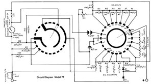
Please help. I have a second hand P.O. meter no 12 C/1. It is a moving coil meter. It reads o.k. on Volts but under reads on Ohms. The zeroing pot does not seem to work. A label inside states that it has thick film components. Why won't it read Ohms accurately? Can it be repaired.

Thanks,

Z.

Parents
  • Generally PO meters were minor customization on the smaller AVO models of the day - 

    is based on it one of these  ?

    Nearly all had a minor variation on this circuit, with more or less ranges, perhaps additional options for audio level tests and some had extra sockets for a shunt for higher current readings.

    Note that the dc input impedance is 20k ohms/ volt, so ~ 50uA for full scale. For AC volts sensitivity  is reduced, typically to half or 1mA full scale, reducing sensitivity to capacitive pick-up. If only modern meters did this.

    Understanding the switch diagram requires you to realise that the rotor bridges the centre and outer contact in the selected positions, and there are two, one on each side of the board or concentric and single sided. So for example in the off position the meter movement is shorted and the ‘+’ terminal is open circuit. 

    In some models one rotor (LH this diagram) is replaced by an ‘ohms or AC volts’ selector,  toggle switch as in the other states it does not do a fat lot…

    Perhaps print out and then colour in the the link in the ohms position(s) and then re-draw the thing unwound with only the paths in circuit.


    Ohms range faults  I'd be looking at battery condition, battery and switch contacts and then the adjuster pot.


    d1948d524a51633a22b9a785b23ff271-original-model_71_circuit.jpg


    The ohms range part can be re-drawn as something like this

    7c993095aa9582f68cafde5cb4b5dafe-original-concept1.png


Reply
  • Generally PO meters were minor customization on the smaller AVO models of the day - 

    is based on it one of these  ?

    Nearly all had a minor variation on this circuit, with more or less ranges, perhaps additional options for audio level tests and some had extra sockets for a shunt for higher current readings.

    Note that the dc input impedance is 20k ohms/ volt, so ~ 50uA for full scale. For AC volts sensitivity  is reduced, typically to half or 1mA full scale, reducing sensitivity to capacitive pick-up. If only modern meters did this.

    Understanding the switch diagram requires you to realise that the rotor bridges the centre and outer contact in the selected positions, and there are two, one on each side of the board or concentric and single sided. So for example in the off position the meter movement is shorted and the ‘+’ terminal is open circuit. 

    In some models one rotor (LH this diagram) is replaced by an ‘ohms or AC volts’ selector,  toggle switch as in the other states it does not do a fat lot…

    Perhaps print out and then colour in the the link in the ohms position(s) and then re-draw the thing unwound with only the paths in circuit.


    Ohms range faults  I'd be looking at battery condition, battery and switch contacts and then the adjuster pot.


    d1948d524a51633a22b9a785b23ff271-original-model_71_circuit.jpg


    The ohms range part can be re-drawn as something like this

    7c993095aa9582f68cafde5cb4b5dafe-original-concept1.png


Children
No Data