This discussion has been locked.
You can no longer post new replies to this discussion. If you have a question you can start a new discussion

Type A R.C.D. 6mA tolerant.

Can I really be confident in the use of a Type A R.C.D. that will tolerate up to only 6mA D.C. current and still operate?

I have a box of old Pifco torch bulbs as used in battery motorists' lanterns. They are filament bulbs rated at 6.2V 0.5 Amp. Their current draw is 500mA. And that for a not very bright torch bulb. That current is supplied via dry cells.

So, the Type A R.C.D.s can only work reliably with a D.C. current of up to 6mA. That is a piddly low current.

Comments please.

Z.

  • I think you mis-state the case somewhat. 

    A 30mA RCD is certain to still trip with an earth fault of 30mA or less, even if there is up to 6mA of perfectly smoothed DC superimposed.

    A type A will still fire on a full amplitude rectified waveform that is not smoothed. 

    As opposed to batteries, where the old sweats drew a distinction between continuous (ripple free) and non-continuous DC (like rectified AC.

  • mapj1: 
     

    I think you mis-state the case somewhat. 

    A 30mA RCD is certain to still trip with an earth fault of 30mA or less, even if there is up to 6mA of perfectly smoothed DC superimposed.

    A type A will still fire on a full amplitude rectified waveform that is not smoothed. 

    As opposed to batteries, where the old sweats drew a distinction between continuous (ripple free) and non-continuous DC (like rectified AC.

    I think that you may have misinterpreted what I wrote Mike. So if 8mA of D.C. is present the Type A R.C.D. will be blinded and will not reliably operate even if 30mA of A.C. earth leakage current is present.

    So, what level of D.C. current was injected by D-Lock earth fault impedance testers of old?

    Please see page 21 towards the end of this link about R.C.D. blinding.

    Z.

  • That is quite a nice illustration, thank you for finding it.

    The implication is that the figure shows a case where  “IRdc > 6mA”

    Is sort of true, but actually  a considerable understatement. As drawn, the example really shows the case when  IRdc >> 6mA, indeed IRdc is still  > 2.8* 30mA.

    The degree of blinding, i.e. the extra current needed to force a trip, will be comparable to the DC bias, not many times it.

    This is quite unfortunate, as I suspect many of the target audience will misunderstand it and over estimate the effect. This is  especially likely given the way magnetic theory seems to be taught to electricians (or not - given the erroneous way some text books showing arrows for the directions of magnetic fields and eddy currents, it is sad but not so surprising that the general awareness often equates with the precision of an exercise in pin the tail on the donkey)


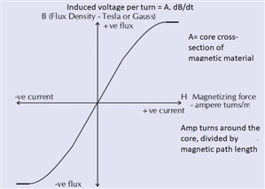
    The degree you move over to the left or right on a BH curve is ‘H’ and is always proportional to the current. The amount of B you get for your H varies once you get outside the linear bit..


    525b717a6f7b6f50cd21442dae46cd57-original-b-h.jpg

    Mike

    PS for anyone whose maths is a bit rusty.

    >>  is vastly greater than, whereas 

    > is just ‘anything greater than’


  • mapj1: 
     

    That is quite a nice illustration, thank you for finding it.

    The implication is that the figure shows a case where  “IRdc > 6mA”

    Is sort of true, but actually  a considerable understatement. As drawn, the example really shows the case when  IRdc >> 6mA, indeed IRdc is still  > 2.8* 30mA.

    The degree of blinding, i.e. the extra current needed to force a trip, will be comparable to the DC bias, not many times it.

    This is quite unfortunate, as I suspect many of the target audience will misunderstand it and over estimate the effect. This is  especially likely given the way magnetic theory seems to be taught to electricians (or not - given the erroneous way some text books showing arrows for the directions of magnetic fields and eddy currents, it is sad but not so surprising that the general awareness often equates with the precision of an exercise in pin the tail on the donkey)

    Mike

    PS for anyone whose maths is a bit rusty.

    >>  is vastly greater than, whereas 

    > is just ‘anything greater than’


    Are we to understand that the small D.C. current needed to drive a typical L.E.D. with series resistor, say 10-15mA, is enough to disable an A type R.C.D?

    Z.

  •  - to reduce its sensitivity by 10-15mA, yes, not to render it useless.

    Mike.

  • Are we to understand that the small D.C. current needed to drive a typical L.E.D. with series resistor, say 10-15mA, is enough to disable an A type R.C.D?

    But it is reasonably difficult to inject such a d.c. current into a LV a.c. circuit - you'd need to create a complete loop/circuit for the d.c. current that included the a.c. circuit (or at least some path through the RCD) - so a single fault from something with a separated source (like a LED driver?) is unlikely to do it. A d.c. fault to earth with a simultaneous N-PE fault elsewhere is sort of the minimum I could imagine at the moment - but then we're into two-faults-to-danger territory, which is generally acceptable anyway (like an earth fault + a broken c.p.c.).

    A few situations are riskier though - e.g. EV chargers where there's d.c. control/signalling circuitry that's deliberately referenced to the c.p.c. or where there are large d.c. currents wandering around exposed- and extraneous-conductive-parts  (e.g. returning traction currents on the Southern Railway) where a single fault could possibly create a d.c. circuit around a.c. conductors - i.e. the sort of situation where type B RCDs get specified (or some alternative like a RDC-DD in conjunction with an A-type RCD).

        - Andy.

  • AJJewsbury: 
     

    Are we to understand that the small D.C. current needed to drive a typical L.E.D. with series resistor, say 10-15mA, is enough to disable an A type R.C.D?

    But it is reasonably difficult to inject such a d.c. current into a LV a.c. circuit - you'd need to create a complete loop/circuit for the d.c. current that included the a.c. circuit (or at least some path through the RCD) - so a single fault from something with a separated source (like a LED driver?) is unlikely to do it. A d.c. fault to earth with a simultaneous N-PE fault elsewhere is sort of the minimum I could imagine at the moment - but then we're into two-faults-to-danger territory, which is generally acceptable anyway (like an earth fault + a broken c.p.c.).

    A few situations are riskier though - e.g. EV chargers where there's d.c. control/signalling circuitry that's deliberately referenced to the c.p.c. or where there are large d.c. currents wandering around exposed- and extraneous-conductive-parts  (e.g. returning traction currents on the Southern Railway) where a single fault could possibly create a d.c. circuit around a.c. conductors - i.e. the sort of situation where type B RCDs get specified (or some alternative like a RDC-DD in conjunction with an A-type RCD).

        - Andy.

    Previous question repeated.

    So, what level of D.C. current was injected by D-Lock earth fault impedance testers of old?

    Quote. "To help explain, it might be worth thinking about some older models of earth fault loop impedance testers, which could cause the RCD to operate unintentionally. To prevent this, some types of earth fault loop impedance testers imposed a DC current on the AC test current. This DC current saturated the magnetic core of the RCD preventing it from tripping under the test condition.

    Where equipment produces an element of residual DC, for example, variable-speed drives is connected to the electrical installation, the DC component can saturate the magnetic core and effectively blind or locks the RCD. This is known as ‘blinding’ and could either prevent the RCD from operating or reduce the sensitivity resulting in a dangerous situation."

    Or did these testers inject ripply D.C?


    Z.

  • I'm not sure about all D-locks, but I have played with one of that  type that injected a few hundred mA between L and N, very well smoothed, and ramping up quite slowly - took over a second . 

    The Zs test pulse from L-E was then in comparison huge (something like 20A or so from memory) but, and this is key, only present for the half cycle of mains that was in the same polarity  as the locking current already applied. In terms of the BH curve, the ‘lock’ current took it up onto one of the flat wings of the curve where more primary amps (H) does not mean any more secondary volts (B'), and then the test pulse took it further from the centre in the same direction. 

    Had the test pulse been reversed so it was un-doing the lock, then a test current comparable to the lock current would have returned the magnetic core back to the high slope region near zero magnetisation, where it does work like a proper transformer, and it would have tripped. Even so the locking current was not enough to fully saturate  all designs of RCD, and even with that tester they still tripped.

    Mike.


    PS

    volts on secondary is volts per turn = B' = dB/dt = rate of change  of magnetisation over time in teslas/second, so you keep the volts right down by changing the current slowly, or for things like ignition coils you get a large back EMF on an inductor by changing current quickly.


  • All this talk about RCDs is bamboozling me. ?

    I think that I may have been misled by my VFD which tripped a type AC RCD, but not a type A one because it failed subsequently and the warranty replacement is compatible with my SRCD.

    As I understand it, there is a hierarchy:

    Type AC: trips on ordinary AC, which is all you have in a traditional filament light, one-speed hoover, electric heater, etc.

    Type A: trips on ordinary AC and rectified AC = pulsating DC, so if there is a diode anywhere, a fault downstream of it would be detected whereas a type AC would (probably) not trip.

    Type F: trips on both of the above and high frequency leakage such as may be found in the synthetic waveform at the output of a VFD. So now we are getting further away from the supply and it seems to me that any fault is unlikely to be of “negligible impedance”.

    Type B: trips on all of the above plus genuine smooth DC. This requires a DC circuit to be in proximity to the mains one so that a fault may develop between them such as in an EV lead.

    “Blinding" is more like getting the sun in one's eyes - the FCD can still ”see", but has to make a little more effort.

    So taking, for example, my chum's new boiler, type A is recommended because of the possibility that a fault in the electronics might make the case live, but with insufficient impedance to trip an MCB. 134.1.1 of BS 7671 simply requires us to “take account of manufacturers' instructions” and the only requirement of RCDs in 415.1.1 is that they have a “rated residual operating current not exceeding 30 mA”. So a judgement might be made that substituting a type A RCD for a type AC one is disproportionate and the installation would comply.

    If I have got the wrong end of the stick, please say so!

  • The thing that most confuses me is blinding in relation to selectivity. For example will a type A (or “better”)  trip at low enough DC currents such that an upstream type AC won't be blinded by DC currents low enough to be passed?

    For a practical example: in a TT system, if an EV charger circuit is protected by a type B, can an upstream time delayed RCD (which guards the whole house, along with RCBOs on each circuit) be type AC, or does it need to be type A or type B, or what?