Good morning everyone, its that time again where if you could spare five minutes of your expertise I would be much obliged!
I currently have to install cabling and controls for a new retrofit underfloor heating system. This system is low profile and involves the pipework laid on a (appx 20mm deep) mat. The existing floor construction is concrete. All pipework will then be set in a deep base levelling compound prior to full tiling of the floor.
The house is fully decorated and the client is unwilling to disturb decoration unless absolutely necessary. It has been suggested to remove coving and run cabling behind to thermostats but this has met firm opposition. There is no access from above other than this.
My current thinking - and it is this that I would appreciate your input on/abuse if you think it's unacceptable :)…
To install 1.5mm BS8436 cable within 16mm flexible conduit in screed where necessary and otherwise behind skirting boards which are being replaced in the course of works. Where in floor (in my created building void) the conduit will be 100mm away from the central heating loops but would inevitably be within the thermal mass of the floor. It will be installed away from where any future installation of carpet would necessitate gripper rods to be nailed down as far as practicable.
Conservatively I have calculated the following derating factors which I hope will be more than conservative enough to make sure Iz is within tolerance for my protective device.
Table 4D2A 1.5mm2 Cable Reference Method A (worst case scenario conservatively selected as more likely to be reference method b). Four core cable rating (three phase (again going conservative to allow for the switch line). Current carrying capacity: 13 Amps At an ambient temperature of 30 degrees
13 x 0.50 = 6.5 amps (derating for a 60 degree ambient temp even though specification says 45-50 degrees for the heating loop water temperature and the ambient temperature of the floor where the cables will be will almost certainly be far below this as they will not be up against them.
6.5 x 0.79 = 5.135 (derating for three grouped cables. Highly unlikely to be necessary (but just in case). These cables are for thermostats only so are almost certainly going to be carrying less than ⅓ grouped current rating.
5.135 x 0.65 = 3.33 amps (additional (bonus) derating for unventilated cabling system as per notes [2 layers of cable - unventilated]
I'm going to use a 3A type B MCB (class 3) at the manifold which will probably also act as the isolator for the central heating controls.
Other than being super cautious can you guys see any wrong-think in my workings - would there be anything else you would consider?
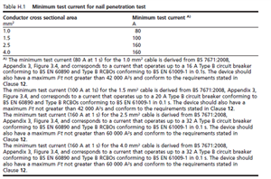
This is the first time I've used BS8436 cable and primarily it is being used to get around the cable not being in permitted zones/at depth within the floor and walls. I've read the guidance with regard to using type B class 3 MCB's at a fault current <5kA which is what will be happening in this installation. I have noticed some suppliers give a maximum energy let through for the protective device (42000A2S) but annoyingly the particular supplier (Atom) that make the cable I have been given do not - I've asked them but am not holding my breath. Do you know whether this maximum energy let through is built into the product standard by any chance. The energy let through of the 3A type B MCB (and probably the 16A type B at the origin of the circuit) is almost certainly going to be far below 42000A2S within an installation with a PEFC <3kA - do I need to look any further into this or is the use of type B MCB's just a ‘given’ with this type of cable.
Hopefully you haven't all nodded off during that. Thanks in advance for any help and advice you can give.


