This discussion has been locked.
You can no longer post new replies to this discussion. If you have a question you can start a new discussion

Principles blank

I am afraid my electrical engineering princIples are letting me down.

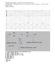
So if I have a standard 400/230v star connected secondary feeding an installation that comprises 3 single phase loads of 10A, 12A and 20A for L1, L2 and L3 respectively,    all in phase, no harmonics. I estimate the neutral current to be 9.16A. If I lose the neutral upstream of the loads what is the voltage to earth? Is it less than 55v? 

  • 9.16x230x1.1. Divided by 10x12x20 = 0.96v  thus less then 70v so complies .

    2317               2400 

    ——

    think that’s how you do it of the top of my head , but I’m not in front of any books it’s a Sunday ! 

  • Lyle

    Yes the neutral current is the square route of the sum of the squares minus the sum of the products which is 9.165A. Using my Xcel calculator with a lost PEN the voltage to earth would be 55V.

    Of course this would be for your phase currents if you were a single user off a transformer. If the output of the transformer supplied multiple users then it would not be a balanced supply on the transformer and the loads on the phases would vary continuously. So you cannot rely on the balanced load option for EV charging as a method of protection set out in 722 when connected to a PME supply.

  • Assuming all 3 loads are resistors, and not either capacitive, or inductive, or worse electronic things that have switch mode supplies that will regulate to draw constant power, so the current they draw goes down as the voltage goes up, then you can solve this by considering each phase in turn to be excited with 230v 0 degrees, 230v 120 gegrees, 230v 240  degrees respectively , and the other 2 to be grounded, and then adding the 3 sets of figures keeping track of the phase shifts and sign reversals depending if current is coming in or out.

    This leads to the same result as others have posted, but it is sometimes useful to remember the how, so you can be sure that the assumptions that underpin it are reasonable.

    Also attached is the same problem solved in LT spice, such computer modelling I find the only reasonably fast way of solving the more complex cases such as constant power SMPS

    #.PDF

    Mike.

  • Assuming all 3 loads are resistors, and not either capacitive, or inductive, or worse electronic things that have switch mode supplies that will regulate to draw constant power, so the current they draw goes down as the voltage goes up, then you can solve this by considering each phase in turn to be excited with 230v 0 degrees, 230v 120 gegrees, 230v 240  degrees respectively , and the other 2 to be grounded, and then adding the 3 sets of figures keeping track of the phase shifts and sign reversals depending if current is coming in or out.

    This leads to the same result as others have posted, but it is sometimes useful to remember the how, so you can be sure that the assumptions that underpin it are reasonable.

    Also attached is the same problem solved in LT spice, such computer modelling I find the only reasonably fast way of solving the more complex cases.