This discussion has been locked.
You can no longer post new replies to this discussion. If you have a question you can start a new discussion

End of Fault current for Parallel lines in Ligting

How to find the end of line fault current for the second case,

If this is a straight forward like below. I calculate all the resistance and reactance of cables in series and arrive at the end of fault current.

However if there are two parallel lines from the JB like in the below image, how do I find the end of fault current?

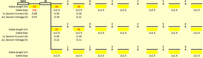
How do I calculate the combined resistance and combined reactance value in this case?

Should I take the maximum resistance which comes out of the three parallel lines for calculating the end of fault current? Also, In general the resistance and the reactance value decreases when connected parallelly

Parents
  • There is almost never a case  to average the resistances of the branches- this sounds like the work of someone better with Excel than with circuit theory. Only if the branches interlink, or if there are short branches on the end of long shared sub-main do the loads on one branch affect the other.

    I suggest ditching the excel and drawing it as resistors on the whiteboard, at least the simplest example.

    Only the first 10m has the volt drop due to the total current, there-after each brack carries its own, but as far as PSSC is concerned, this is small - with kA flowing to the faulted branch, an amp or 3 down another is not going to change much.

    As sanity check that does not need the excel, you can assume that 1m of 1mm2 wire is 16 milliohms when cold, or more like 19-20 milliohms when hot, and this scales as you expect with cross-sections. (so 10m of 10mm2 is the same as 1m of 1mm2 etc. ) It then simplifies  to some resistors in series for the wire, and in /// for the loads. (cable normally has equal live and neutral current (lets ignore 3 phase for now) so the volt drop to the load is the live voltage falling on the way to the load, and the neutral voltage rising.)

    Mike.

Reply
  • There is almost never a case  to average the resistances of the branches- this sounds like the work of someone better with Excel than with circuit theory. Only if the branches interlink, or if there are short branches on the end of long shared sub-main do the loads on one branch affect the other.

    I suggest ditching the excel and drawing it as resistors on the whiteboard, at least the simplest example.

    Only the first 10m has the volt drop due to the total current, there-after each brack carries its own, but as far as PSSC is concerned, this is small - with kA flowing to the faulted branch, an amp or 3 down another is not going to change much.

    As sanity check that does not need the excel, you can assume that 1m of 1mm2 wire is 16 milliohms when cold, or more like 19-20 milliohms when hot, and this scales as you expect with cross-sections. (so 10m of 10mm2 is the same as 1m of 1mm2 etc. ) It then simplifies  to some resistors in series for the wire, and in /// for the loads. (cable normally has equal live and neutral current (lets ignore 3 phase for now) so the volt drop to the load is the live voltage falling on the way to the load, and the neutral voltage rising.)

    Mike.

Children
No Data