This discussion is locked.
You cannot post a reply to this discussion. If you have a question start a new discussion

Neutral and Earth voltage with battery storage

Hi,

I have a battery storage system which is grid tied. This has been G98 registered. The battery has a grid tie and a UPS backup circuit.

The system works as expected, however when in UPS backup mode, I have noticed something that I need to clarify.

When in normal grid tied mode, the following voltages are recorded on the UPS output: 

L-N = 230V 

L-E = 230V 

N-E = 0V 

When in UPS mode, the following: 

L-N = 230V

L-E = 130V

N-E = 130V 

The manufacturer confirmed that when in UPS mode, a N-E link is made automatically and disconnected automatically. I have contacted them but being in China, they are slow to respond.

What I noticed, is that if you switch off loads on the UPS output, the voltage between L&E slowly increases to around 200V. I haven’t as yet tested to see if the same is apparent with N&E. 

Any ideas? This is an inverter so I am unsure if this sort of reading/phenomenon is normal? 

Thanks. 

Parents
  • The manufacturer today confirmed the following: 

    A “N-E” bond is created on the UPS backup output when in backup mode. 

    Voltages of 130V between N-E and L-E are normal, due to capacitances in the UPS output.

    That doesn't make sense to me - any capacitive coupling between N and PE should be shunted out by the N-PE link (if it's correctly being applied).

       - Andy.

  • I thought that too

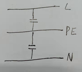
  • The manufacturer came back today with this drawing: 

    The UPS output is a true UPS, not the same as a standard generator which requires a hard/mechanical neutral to earth bond. This capacitor arrangement is switched in only when in UPS mode. 

    The voltages between L-E and N-E are because of these capacitors, roughly half of the L-N voltage.

    The UPS is regulated and approved to various UPS standards.

    Looking at this also, RCDs would also function normally in UPS mode. 

  • Well that's not compatible with their statement "A “N-E” bond is created on the UPS backup output when in backup mode. ".

    The UPS/Generator comparison for N-PE links isn't helpful - it's more a matter of size rather than type - large UPSs will have N-PE links and small generators (typically <3kVA) often run without them.

    It's all down to the chosen method of providing protection against electric shock - you can have electrical separation where shocks (to Earth) are prevented by ensuring that the system's connection to Earth is so poor that a dangerous shock current can't flow (i.e. no N-PE) link, or you can have an N-PE link and have automatic disconnection of supply (ADS) to mitigate against shocks. (Or there are other methods such as double/reinforced insulation or SELV/PELV).

    The complication here is that BS 7671 only recognises separation for supplying single items of current using equipment in normal circumstances - so you can't use it for supplying multiple items in a fixed installation. And the Electricity Safety Quality and Continuity regulations (law) demands that your system complies with BS 7671 if you have embedded generation.

       - Andy.

  • Hi, and thanks.

    Yes, I think the language barrier is somewhat prohibitive. I asked if there was a N-E link, and they responded with a yes but clearly meant there was some “form”’of link. 

    During normal operation, the UPS output of the inverter operates the same way as the non-UPS side. If you measure L-N, L-E the voltages are 230V. If you measure N-E the voltage is 0V.

    It is only when the UPS is in output mode, that the voltages between N-E and L-E are at 130V, because of how the inverter operates. 

    The supplier has confirmed that MCBs and RCDs would operate normally during backup mode, therefore providing protection against electric shock. 

    How does this operation contravene BS7671 specifically? 

Reply
  • Hi, and thanks.

    Yes, I think the language barrier is somewhat prohibitive. I asked if there was a N-E link, and they responded with a yes but clearly meant there was some “form”’of link. 

    During normal operation, the UPS output of the inverter operates the same way as the non-UPS side. If you measure L-N, L-E the voltages are 230V. If you measure N-E the voltage is 0V.

    It is only when the UPS is in output mode, that the voltages between N-E and L-E are at 130V, because of how the inverter operates. 

    The supplier has confirmed that MCBs and RCDs would operate normally during backup mode, therefore providing protection against electric shock. 

    How does this operation contravene BS7671 specifically? 

Children
No Data