This discussion is locked.
You cannot post a reply to this discussion. If you have a question start a new discussion

EV chargers in basement car parks - earthing

I'm working on a project that will have a few 7kW single phase EV chargers fed from a three phase system.

The chargers will be located in the car park in the basement of the building. The chargers have built-in type B RCDs.

I was hoping someone might be able to provide some guidance in relation to the earthing arrangement. 

Strictly speaking, the chargers are "indoors" and within the equipotential zone. But since the installation is in the basement, would it be best to treat it as an outdoor installation and allow for installing separate earth rods? Or will this be problematic with any potential metalwork in the ground?

  • Mr Graham Kenyon is the expert in such matters so all I can do is say what I would do. I have a strong opinion that conversion to TT is a poor substitute to integral  open pen protection. Likely 722.411.4 indent (v) which for three phase is probably indent (iii) with a means of disconnecting the contactor when small values of current appear in the protective conductor to the car when someone touches the car on an open pen fault.

    We are currently installing 10 twin head units in an open car park and it pains me to convert to TT. The manufacturer is from a Nordic country, where, apparently, they don’t see the risk quite the same as we do.

  • Oh and by the way, no one installing chargers should be without a copy of the COP for Electric Vehicle Charging Installation and should be familiar with its contents.

  • Section 8.2.3 of the IET Code of Practice for EV Charging Equipment Installation (4th Edition) begins with the following, if PME aplies:

    8.2.3 PME Supply
    Inside Buildings
    For electric vehicle charging equipment installations supplied from installations with a
    PME supply (part of a TN-C-S system), the charging equipment may be connected to the PME earthing arrangements if the charging equipment is located inside the building and if it can be ensured that the vehicle being charged will always be within that same building (for example an underground car park, multi-storey car park, and so on).

    Balancing loads is recommended, though.

    I agree with what Lyle says about the issues associated with a separate earthing arrangement in this particular case.


    What is probably more tricky and worrying would be a fire risk assessment - has this already been carried out, or the existing one been updated to take into account EV fires?

  • conversion to TT is a poor substitute to integral  open pen protection.

    Both are flawed in my opinion - if in different ways. TT is entirely reliant on a delicate RCD operating reliably - which we know they don't always do.

    On the other hand single phase open-PEN detection system that work by sensing the L-N/PE/PEN voltage straying outside normal limits are fundamentally flawed where a 3-phase distribution system is in use as there are a whole range of 3-phase not-quite-balanced balance situations where the PEN can be an awful way adrift from 0V but L-PEN voltage on a particular phase can still be within tolerance. Some manufacturers also add c.p.c. current monitoring (a bit like the old VoELCBs) to mitigate the danger a bit - but that relies on someone getting a shock before disconnection occurs. Then the whole thing is driven by electronics and a mechanism to release contacts ... very much like an RCD ...  so we're pretty much back to the same reliability question we have for TT. It's because of these flaws o-pen devices aren't recognised for use in installations with 3-phase available - fundamentally a much better job can be done by referencing to an artificial neutral point derived from all 3 phases.

    If it's indoors, I'd stick with using the building's Earthing system and keep things simple.

       - Andy.

  • but that relies on someone getting a shock before disconnection occurs.

    You mean, a bit like Additional Protection by RCD on Class II equipment or a live conductor in a severed flex? But in that case it's definitely the full line to Earth voltage, rather than "might be over 70 V"?

  • Then the whole thing is driven by electronics and a mechanism to release contacts ... very much like an RCD ...  so we're pretty much back to the same reliability question we have for TT. It's because of these flaws o-pen devices aren't recognised for use in installations with 3-phase available - fundamentally a much better job can be done by referencing to an artificial neutral point derived from all 3 phases.

    Smoke and mirrors! I'd prefer to stick with 3 phases even if a car can cope with only one at a time.

  • On the other hand single phase open-PEN detection system that work by sensing the L-N/PE/PEN voltage straying outside normal limits are fundamentally flawed where a 3-phase distribution system

    I've also been thinking about this statement. I think "fundamentally flawed" is far too strong - see below.

    there are a whole range of 3-phase not-quite-balanced balance situations where the PEN can be an awful way adrift from 0V but L-PEN voltage on a particular phase can still be within tolerance.

    But, with the voltage range in BS 7671, only on any one phase downstream of the broken PEN ... plus the fact that, in a real broken neutral situation, the neutral (PEN in this case) voltage moves around as loads change - we're definitely not talking about a static situation of perpetual non-detection.

    So, I think the reality of the 722.411.4.1 (iv) device is perhaps Not ideal, but offers an improvement over doing nothing.

  • I think "fundamentally flawed" is far too strong

    Maybe so. What I meant to suggest is that while most safety approaches are flawed in some way or another - usually it's the case that the underlying theory is sound but it's let down by real-life implementation details - sticky contacts, weak springs, accuracy of measurements, broken wires and so on. Whereas with L-N voltage monitoring for open PEN detection, there's a pretty obvious gap even in the underlying theory (the "fundamentals" in my mind) - thus there are a (small) range of conditions where it cannot detect a broken PEN even when the whole device is in perfect condition.

    Certainly the chances of having problems may be small in practice - and additional features such as latching off after an out-of-range voltage event has been detected and c.p.c. current monitoring can help to reduce the risk even further (although 722.411..4.1 doesn't appear to require either of those).

    Not ideal, but offers an improvement over doing nothing.

    I think that sums it up nicely!

       - Andy.

  • Whereas with L-N voltage monitoring for open PEN detection, there's a pretty obvious gap even in the underlying theory (the "fundamentals" in my mind) - thus there are a (small) range of conditions where it cannot detect a broken PEN even when the whole device is in perfect condition.

    I mean there is a similar gap in RCDs, the assumption that an indefinite shock current in the range 15-30 mA is safe for the whole population, when the evidence does not really support that.* In both cases there is a probability that a perfectly functioning device does not produce the expected safety outcome, but this may be OK, depending on what that probability is.

    *Our limits mostly being based on Dalziel's work, which was arrived at largely by tests on fit, young, American men. Optimal limits for women, the elderly and the very young are believed to be lower than 30 mA.

  • Hi everyone,
    I would be happy to share with you a safety and regular matter according to the plan is simple and easy and without any risk to the mind.

    Pedestrian / cable ducts - permanently breaker
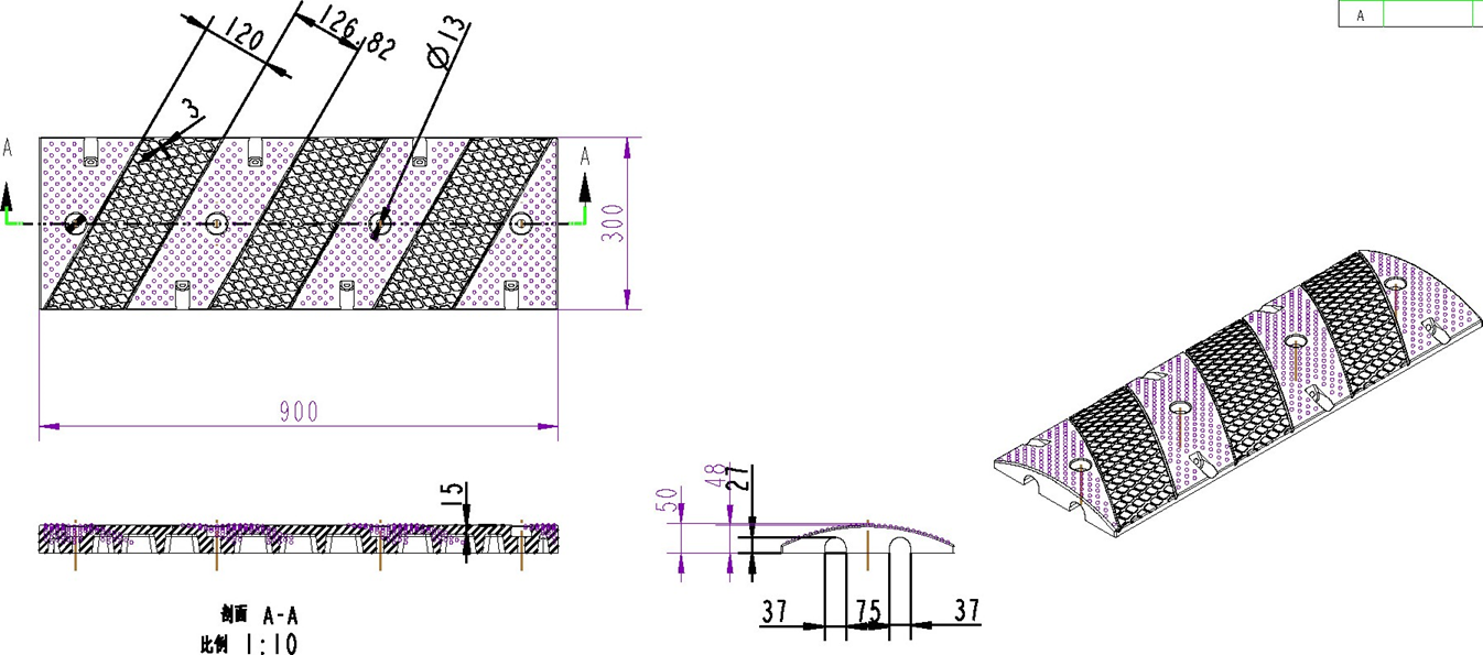
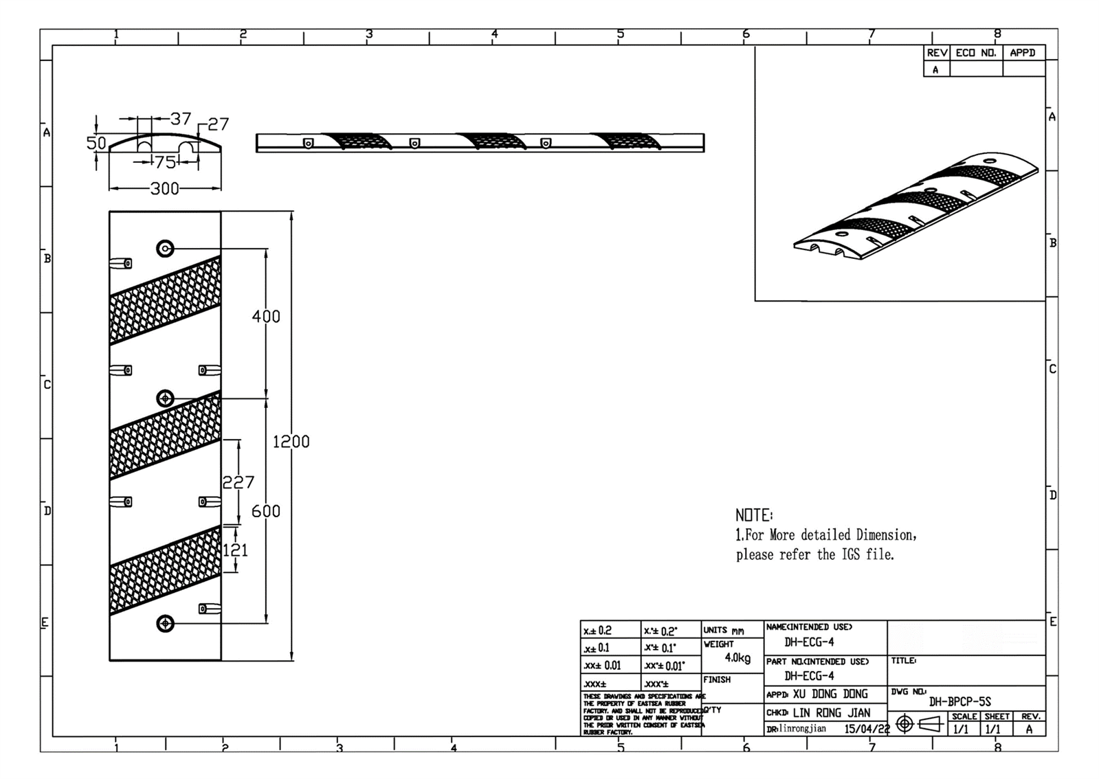
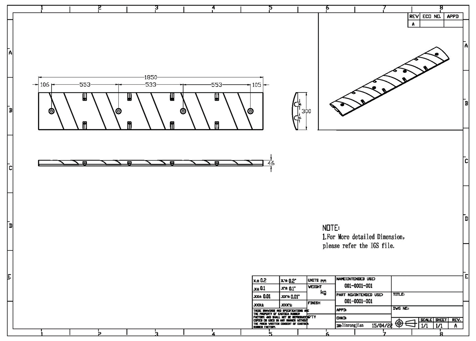
    Stepping ducts for permanent installations in the form of a small breaker 50 mm high with 2 internal ducts for transmitting electrical cabling / piping.

    Durability for vehicles weighing up to 20 tons (permanently installed at a travel speed of 10 km / h). Made of high-quality EPDM hard rubber for all weather conditions.

    The canals have 2 separate lower slits, each with a width of 36 mm and a maximum height of 27 mm (in a rounded configuration upwards).

    3 models in 3 different lengths: 900 mm, 1200 mm, 1850 mm + option to add a final set separately (part number DH-SP-6E) - below are the three models:

    • DH-SP-26M - 1.85 meters long

    • DH-SP-28M - 0.9 meters long

    • DH-SP-29M - 1.2 meters long