The IET is carrying out some important updates between 17-30 April and all of our websites will be view only. For more information, read this Announcement

This discussion is locked.
You cannot post a reply to this discussion. If you have a question start a new discussion

Phase rotation

Hi all I think its fairly common knowledge that the phase sequence on Merseyside is different from most of the rest of the country  but what I didn't know is that South London  is also different   Blue Red Yellow apparently someone got it mixed up at battersea power station and its been that way since the 1930s is this common knowledge ? Must be very confusing when wiring up motor loads  and other phase sensitive gear its amazing to think one cock up  70 plus years ago is still having an effect now
  • I've known about it since very early on in my time in the industry. Initially in Merseyside, but I was at that time told about some other locations around the country with the same issue. I guess if you are used to working on three-phase systems, and have worked around the country, you'll get to know about it soon enough.

  • A phase rotation indicator is a good idea. On stuff that has to travel abroad, I have been known to design one in permanently as part of the power conditioning going in, as it is only a neon indicator, a capacitor and some resistors. Along with other things like some phase and N-E voltage checks.... If you think things are a bit funny here you need to travel a bit south or east  to realize we are actually quite good compared to some places.
    Mike.

  • and York and Middlesbrough ... in fact I'm at the stage now on not knowing which way around is considered "normal" and which is "reverse". I think we just have to accept that there's no standard.

    Actually some of the older continental practice was in some ways better adjusted - since they used the same colour for at least two of the three lines (e.g. L1 brown, L2 & L3 black)  - that way two could be swapped around as necessary without anything appearing odd and it 'managed expections' rather better.

        - Andy.

  • Interesting replies thankyou all. I'm not surprised some other country's have problems  in that respect after all some can't even maintain a steady 220 volt supply. It's obviously a lot more common than I thought  here in dorset we do at least manage to maintain a normal R Y B rotation thank hoodness

  • Well I make my phase indicator light up happy if the rising edge zero crossings occur in the order L1, then L2 then L3.  Folk can then move the wing nuts and coloured sleeves around on the other end  until the happy light comes on, all 3 phase lights are more or less equal brightness and the NE light is off.  Only then should the main switch be closed.

    Mike

  • I can see that when the many power stations in London supplied just their local boroughs, they could choose their phase rotation. I can also see that the phase rotation can be changed at any transformer, but surely the rotation must be the same throughout the National Grid?

  • How can we tell the difference between say R Y B or Y B R or B R Y they are all say clockwise and anything else would be anticlockwise say. Is there a marker dip or something on perhaps Red to let us know it`s not yellow or blue? 

    PS - I think it might have been Mapj1 or Graham Kenyon did a little sketch of a simple rotation check cct a while back. Could we see that again?

  • I emailed that circuit to you about ten years ago - I'll dig it up again;-)

    As far as I know there is nothing special about first phase, just that as soon as you have chosen first phase, then the choice of second defines the rotation direction

    Absolute timing is not maintained, indeed "red" in some districts is the same as the  phase called "blue" in another. This is done to counter the tendency to load up red 1st, so the DNOs cycle them to balance things up a bit. They are however very careful to retain the rotation sense.

    Mike.

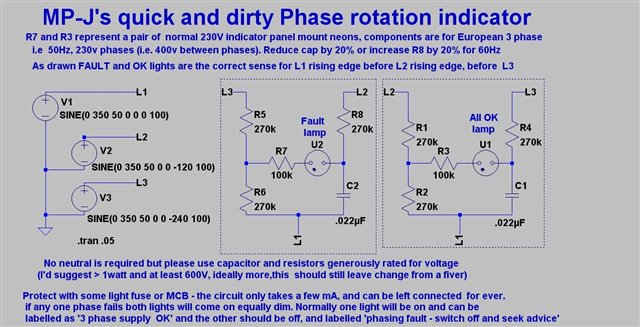
  • OK that circuit is as follows. Each neon lamp is strung between 3 resistors and a capacitor - an RC phase shift between 2 phases can be set to ~ 60 degrees to be comparable to the 'mid phase' voltage derived from a pure resistive divider between the other 2 phases - that lamp does not light.

    Do the same again with the phases reversed and the light now sees slightly more than single phase voltage, and illuminates. 
    Does not work properly with inverters that do not create a clean sinewave.

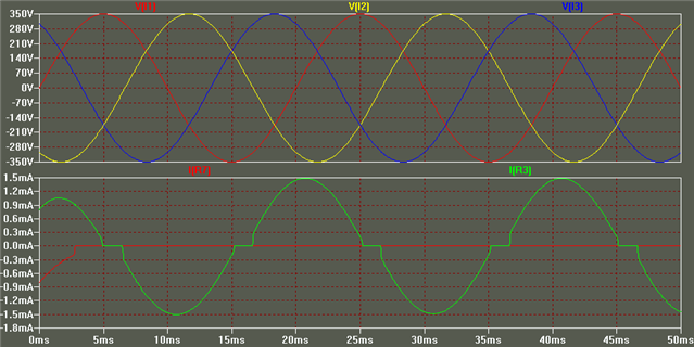
    The waveforms show that when the voltages are as below (red rises from zero volts on the far left, and the next one to do so is yellow, 1/3 cycle later) peaks of 230V AC are approx +/- 350V

    ~The lower traces show one neon (green curve)i s passing current and the other (red line) is not.

    I have used variants of this circuit over many years built into  kit that has to travel a lot.

    Mike.

  • Thanks Mike