The IET is carrying out some important updates between 17-30 April and all of our websites will be view only. For more information, read this Announcement

This discussion is locked.
You cannot post a reply to this discussion. If you have a question start a new discussion

Electric Motor Configurations

So I have a (new) 1.5kW motor.

The motor rating plate declares the machine as being 380V 60Hz 3 phase, 3.96A and then ' WIRED IN STAR'.

The rating plate only gives details about the star configuration - it doesn't mention delta.

Looking inside the terminal box, all 6 wire ends are brought out - three being linked to form the star point.

Removing the star point reveals that all three coils are indeed electrically separate & the opposite ends are all displaced by one position as they would need to be if one was to reconfigure this machine into delta by turning the three links through 90 deg.

My question for the learned forum - why hasn't the manufacturer given any details about the delta configuration on the plate? Indeed he has even specified 'WIRED IN STAR'.

Why would he wish to rule out the use of the delta configuration? What badness might result from me re-configuring into delta & running from 220/3/60? The windings don't care whether they are in star or delta - if I apply 380/3/60 in star or 220/3/60 in delta the winding still has the same voltage across it.

What am I missing?
Parents
  • Also, a surprising fact is that the peak value of a first harmonic in a square wave  exceeds that of the square wave .

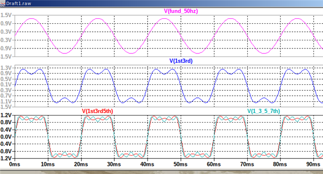
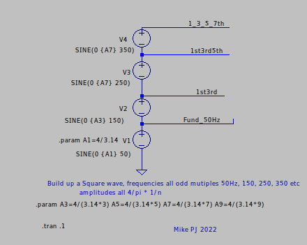
    By a factor of 4/pi because of course when you add in the next term in the expansion at 3F, there is a down kick at the top of the wave, knocking the peak of the fundamental down. Consider this....

    A series of AC voltages at 50Hz, 150Hz, 250Hz etc. with amplitudes A3, A5 A7 etc all correctly scaled. At the bottom tap we see the waveform of the fundamental sine wave only, at the next tap up  the 50Hz plus the 150Hz term, etc.

    So note the voltage scales on the Y axes - the top fundamental only sine wave is swinging  +/- 1.4v pk or so. The next graph shows that plus the next largest term the 150Hz sine wave - now this speeds up the zero crossings and knocks down the peak so swing is a touch under 1.2v. The lower traces  show there is no cheating, and as we add more and more terms it just gets more square and looks more like the ringing square wave we expect in a bandwidth  limited system.
    Some times flipping to the time domain view like this can be  more informative than the spectrum,,,
    Mike

Reply
  • Also, a surprising fact is that the peak value of a first harmonic in a square wave  exceeds that of the square wave .

    By a factor of 4/pi because of course when you add in the next term in the expansion at 3F, there is a down kick at the top of the wave, knocking the peak of the fundamental down. Consider this....

    A series of AC voltages at 50Hz, 150Hz, 250Hz etc. with amplitudes A3, A5 A7 etc all correctly scaled. At the bottom tap we see the waveform of the fundamental sine wave only, at the next tap up  the 50Hz plus the 150Hz term, etc.

    So note the voltage scales on the Y axes - the top fundamental only sine wave is swinging  +/- 1.4v pk or so. The next graph shows that plus the next largest term the 150Hz sine wave - now this speeds up the zero crossings and knocks down the peak so swing is a touch under 1.2v. The lower traces  show there is no cheating, and as we add more and more terms it just gets more square and looks more like the ringing square wave we expect in a bandwidth  limited system.
    Some times flipping to the time domain view like this can be  more informative than the spectrum,,,
    Mike

Children
No Data