This discussion is locked.
You cannot post a reply to this discussion. If you have a question start a new discussion

Harmonics in line

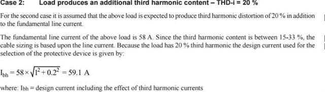
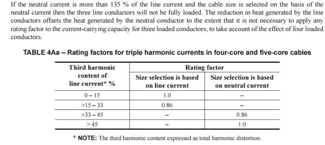
Can someone advise where the first formula in case 2 in section 5.5.2 in appendix 4 springs from. The one where Ibh=the root of 1squared plus 0.2 squared? I thought current in the line due to harmonics was accounted for by applying the 0.86 from the table referred to.

  • well the 1 and the 02 are the relative amplitudes of the fundamental and harmonics respectively.

    20% of 1 is 0.2,

    They are added as if they are at right angles, pythagorically if you like as they are considered  independent terms. This is an approximation, but for the general case we do not know the relative phase of the 3F and 1f components.  So with 20% distortion, each phase line has 20A of 3F for every 100A of 1F.

    This leads to  the additional heating of the 3 phase cables

    But the neutral, previously in perfect balance, so cold with a pure resistive 3 phase load now carries the 3f currents from all 3 phases, and being 3rd harmonc, they add in perfect phase being offset in time by 1/3 of a cycle at 1F, a whole cycle time at 3F, so if we had 100A of 1F and 20A of 3F in each phase in the neutral we would have 60A, and this is more heat that eats further into the cable rating.

    The table

     is aimed at those wanting a simple life and includes both line and neutral wire heating.

    Up to 15% do not bother, and up to 33% assume a de-rating of 86%

    Now as above clearly for 20% for lines alone you could assume 98 point something percent and end up with 59/58.
    however even putting in 33% does not reach 86% by a long way, more like 6% de-rating so 94%

    The rest is the heating of the neutral core.

    I hope this helps, but come back if it needs a bit further explain - it is getting late

    M

  • Well thank you so much, Mike. You are a star! That was bugging me. I am off the coast of Norway at the moment (happily not in the water but in a nice new cruise ship). Internet connection is slow and sporadic, a bit like myself really. 
    What was confusing me, apart from the phasor addition bit, was that in case 2 they have increased the line current by, as you say, the quadrature addition of fundamental and 3F which resets the line current to 59.1A. Now in their example, the resetting of the line current has no effect on the top line as they still use a 63A device as the grouping situation has 3 other cables subject to simultaneous overload hence an In value of 63A is used. So if I choose to provide similar overload protection but wish to consider my circuit grouped with 3 others that are not subject to simultaneous overload, I would use 59.1A on the top line and apply the divisors as they have, including the 0.86? Does that seem correct?

  • Glad you are not in the water, salt, water and electrics can be a frisky mix. (I have used long plastic tubes of washing soda solution as bleeds on EHV lab kit, but never NaCL, always too corrosive at the plumbing fittings )

    So back to the effects of heating due to non sinusoids.

    The chosen examples they give are not perhaps the best illustration, as you say it does not affect the OPD, but it does alter the cable rating, by grouping the 3 lives, themselves not much warmer, with a surprisingly warm neutral.
    So yes the cable thermals are now not 3 hot wires and one cool, but 4 hot wires and the current rating of 60A or whatever needs to be met with the heated neutral, so look for a cable that can handle 60A/0.86 of 3 phase when there is negligible neutral current.

    The reason that 33% THD is magic, is that is the point when the total RMS neutral current now equals the current in any one line.

    As I said above it is a bit of a hack as the the relative phase of the 1F and 3F on the line does have an effect, but all dwarfed by the neutral conductor heating which is much like a grouping problem.

    These plots are voltages from something else actually, but the same things happen with currents.
    note also that the skin depth and rise of inductance voltage drop compared ot resistive is proportional to frequency, so if cables are large, then the 50Hz ratings are not right anyway, and layout in quadrifoil rather than trefoil plus one to get the magnetic field effects down matters more too..
    Mike.