This discussion has been locked.
You can no longer post new replies to this discussion. If you have a question you can start a new discussion

TT earthing arrangement

I have found two earth electrodes at each , this is due to supply authority providing earth elecrode at their main panel and contractor supplying earth electrodes local to two seperate installations. I have two questions:

Is there an issue with using more than one earth electrode for each installation i.e. both the supply authority electrode connected to the installation via feeder cable SWA + supplimentary earth cable, and a local earth electrode connected to the main earth bar of each installation?

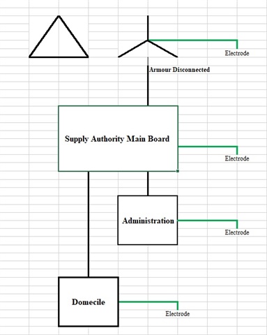
The project consistes of two buildings, one is a administration building and the other is a residential building with multiple demociles, both are approx 500m from the supply authority earth electrode. 

I note the measured Earth Fault Loop Impedance values are low enough to comply with BS7671.411.4.202, Table 41.3 and as such they comply with Note 1 of BS7671.411.5.2. while I understand the use of  Overcurrent Protection Devices without RCD protection for final circuits are considered acceptable, are there any issues I should take into account.

Note I am in the middle east and the ground is as dry as it gets there has been no rainfall or water on the ground since early April therefore the contribution of the general mass of earth to the fault path measured values are as high as they will ever be.

Parents
  • Oh hang on. A measured  ELFI of 0,2 ohms is not going via any normal TT electrode, except perhaps one that has stabbed and connected to the neutral of the supply  cable underground... That sort of figure is more credible for the resistance of the live core alone of the 500m cable or at the load end R1 + R2 of a final circuit, but that is not the fault path, you have to add in Ze.

    The ten ohms loop in dry ground is credible but still remarkably good , (consider about 20 - 200ohms  in the UK for a single 4 foot rod 5/8" diameter )  what is the electrode type ? to get to 0.2 ohms you must have buried a modest battleship, and so must the supply company at the substation.

    These figures do not gel. What exactly was measured and how ?

    Mike.

Reply
  • Oh hang on. A measured  ELFI of 0,2 ohms is not going via any normal TT electrode, except perhaps one that has stabbed and connected to the neutral of the supply  cable underground... That sort of figure is more credible for the resistance of the live core alone of the 500m cable or at the load end R1 + R2 of a final circuit, but that is not the fault path, you have to add in Ze.

    The ten ohms loop in dry ground is credible but still remarkably good , (consider about 20 - 200ohms  in the UK for a single 4 foot rod 5/8" diameter )  what is the electrode type ? to get to 0.2 ohms you must have buried a modest battleship, and so must the supply company at the substation.

    These figures do not gel. What exactly was measured and how ?

    Mike.

Children
  • Hi Mike,

    The 0.22 ohms was the Ze at the domecile installation main panel, not the electrode measurement, yes I am as confused as you.

    For measuring the earth electrode resistance  between authority and transformer, we removed the main panel electrode connection isolating the main panel electrode from the local electrodes at the installations.

    Took a flying lead and connected between the disconnected main panel electrode main earh lead and the transformer electrode, this result returned approx 7ohms.

    I have physically observed that the armours of the main panel feeder at the transformer are not connected therefore there is no physical metalic earth connection between the transformer and the main panel. I have inspected all the main panels and there are no N-E links.

    A sample of two final circuits EFLI were tested and returend results which comply with Table 41.3.