This discussion has been locked.
You can no longer post new replies to this discussion. If you have a question you can start a new discussion

TT earthing arrangement

I have found two earth electrodes at each , this is due to supply authority providing earth elecrode at their main panel and contractor supplying earth electrodes local to two seperate installations. I have two questions:

Is there an issue with using more than one earth electrode for each installation i.e. both the supply authority electrode connected to the installation via feeder cable SWA + supplimentary earth cable, and a local earth electrode connected to the main earth bar of each installation?

The project consistes of two buildings, one is a administration building and the other is a residential building with multiple demociles, both are approx 500m from the supply authority earth electrode. 
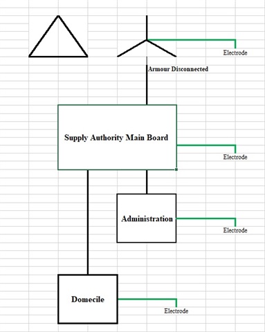
I note the measured Earth Fault Loop Impedance values are low enough to comply with BS7671.411.4.202, Table 41.3 and as such they comply with Note 1 of BS7671.411.5.2. while I understand the use of  Overcurrent Protection Devices without RCD protection for final circuits are considered acceptable, are there any issues I should take into account.

Note I am in the middle east and the ground is as dry as it gets there has been no rainfall or water on the ground since early April therefore the contribution of the general mass of earth to the fault path measured values are as high as they will ever be.

  • the supply authority electrode connected to the installation via feeder cable SWA + supplimentary earth cable,

    EFLI measurement of a final circuit returned 0.24 Ohms

    Are we sure this isn't really a TN setup?

       - Andy.

  • Hi David,

    Submain protection was not a concern as 411.3.2.4 allowed 1 second max for disconnection of distribution circuits and I have required ELR's for all submain circuits. I have not seen amendment 2 yet does this affect 411.3.2.4?

    I agree, I think there is a neutral earth fault somewhere, I have asked for switchgear flash test results as I suspect there may be a damaged insulation of a neutral support in the panel, will test this out tomorrow, as previously advised there are no N-E links in any of the switchboards.

  • Hi Mike,

    I am suspicious that there may be a damagfed insulated neutral support in a switchboard, either the submain or main. Will be testing all main and submain boards N-E insulation resistance tomorrow.

    If that does not provide answers will request authority retest their feeder cables N-E insulation resistance.

    Thanks for the relpies today, I had overlooked the basics when I was asking the original question, your replies made me wonder how the EFLI could possibly be lower than the earth resistance even if they were good results. As you say, unless there was a battleship buried it makes no sense Smiley

    Will let you guys know the results of the tests tomorrow and if problem has been identified, if not, will ask for more advice Slight smile

  • Hi Andy,

    As I replied to Mike and David, I will be looking at N-E insulation tests tomorrow, hopefully resolves the issue.

    Thanks for the response will post result tomorrow to close the discussion with findings and the solution.

  • Hi Guys,

    Thanks for all the help, we tested everything and found the issue was with factory wiring of DB's N-E faults there appears to be an issue with some of the RCBO's in four of the DB's, which will be replaced. Apparently they do not do factory tests or QA/QC checks before shipping. I expect that is why we were engaged to validate the testing.

    Again, thanks for all your questions and advice.

  • Very glad there was a clear problem to be found, kind of makes it worth it.  I presume now the Zs is more like a slack handful of ohms, and RCDs are needed in more places after all ;-)

    Mike.

  • Hi Mike,

    Yes a reliefe indeed.

    We also isolated the each local buliding electrode from all other return paths and measured 28 Ohms across the disconnected incoming feeder armour (with supplimentary) and the isolated building electrode, which I thought was low but this time the numbers chrunch, with the main panel electorde approx 7 Ohms, the measured EFLI at the building incomers was measured at approx 6.5 Ohms.

    Another problem found during the electrode isolation process above was that the lightning network was connected directily to the building electrode, via underground copper tape. This was removed and will remain so.

    Again thanks for your advice.   

  • Another problem found during the electrode isolation process above was that the lightning network was connected directily to the building electrode, via underground copper tape. This was removed and will remain so.

    It's usual to keep all the earthing systems solidly bonded together (test links at most between them) - where the lightning and power earths are separate you can get flash-over from the lighting system to the electrical system which can cause great damage, unless the two systems are separated by a very significant distance (several metres) throughout. Presumably there are some beefy SPDs too.

      - Andy.

  • BS EN 62305

    Z.

  • Hi Andy,

    Yes, thanks, I advised them that the lightning protection system should be connected at the main earth bar while the external extraneous conductive parts are bonded to the lightning protection system. I believe this is BS62305 compliant.

    There are SPD's at each building main panel.