This discussion has been locked.
You can no longer post new replies to this discussion. If you have a question you can start a new discussion

TT earthing arrangement

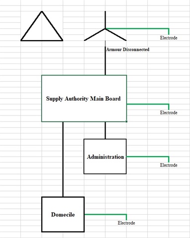
I have found two earth electrodes at each , this is due to supply authority providing earth elecrode at their main panel and contractor supplying earth electrodes local to two seperate installations. I have two questions:

Is there an issue with using more than one earth electrode for each installation i.e. both the supply authority electrode connected to the installation via feeder cable SWA + supplimentary earth cable, and a local earth electrode connected to the main earth bar of each installation?

The project consistes of two buildings, one is a administration building and the other is a residential building with multiple demociles, both are approx 500m from the supply authority earth electrode. 
I note the measured Earth Fault Loop Impedance values are low enough to comply with BS7671.411.4.202, Table 41.3 and as such they comply with Note 1 of BS7671.411.5.2. while I understand the use of  Overcurrent Protection Devices without RCD protection for final circuits are considered acceptable, are there any issues I should take into account.

Note I am in the middle east and the ground is as dry as it gets there has been no rainfall or water on the ground since early April therefore the contribution of the general mass of earth to the fault path measured values are as high as they will ever be.

  • In general there is no issue with adding extra electrodes, or indeed any extra metal that is not perhaps good enough to be the sole electrode - building steels come to mind. The better you can get a grip on the terra-firma is always good.

    Unless the electrodes are massive, then 500m is more or less the same as 'infinite' or at least the resistance  to the far side of the planet would only be a few % more , so no concerns about being fooled by electrode near fields overlapping.

    At the substation transformer there may be combined or separate HV and LV side earthing, the key thing is that if HV shorts to the transformer core or metal tank or whatever, there is not an excessive jump in the LV side neutral to true earth voltage. Which is done will depend on ground resistances and the impedance of the HV side supply, and possible fault to earth current.

    What must be avoided is earthing zones that are not metallically interconnected coming within reach of each other - say 2m if accessible.

    I am a bit puzzled by the 'armour disconnected' comment - is this to prevent a problem with circulating current - if it means there is no metal CPC at all between the TX and the suppliers main panel, then this is a TT substation, which would be unusual. Or there may be an N-E link at the suppliers main panel and there is in effect a PEN back to the transformer and it is TNC mains - can you clarify which is it please ?
    M.

  • Hi mapj1,

    There is no earth connection between the transformer and the main panel or N-E link in the main panel, as you say, it is a TT substation, the regional regulations identify TT as the standard earthing arrangement.

    The Transformer earth electrode is approx10m from the main panel earth electrode providing an electrode to electrode resistance of approx 7 Ohms through the general mass of earth.

    The installation designer has omitted to to provide RCD's for every final circuit (this, they advise, is by accident) as they are used to designing TN-C-S systems and were not aware that the regional standards were for TT.

    I have advised if there is no problem with the local electrodes supplimenting the authority electrode, and if the measured EFLI values are below those provided in Table 41.3 then there maybe no need to add RCD's, where these parameters are not met then RCD's mst be installed.

    The only issue then is that system voltages for the region are 415/240 volt and the Max EFLI should be adjusted to suit (max 264v), which i am currently working on.

  • That sounds more or less OK. Of course when the numbers are processed, an RCD of some sort will  be needed in most final circuits - a 7 to 10 ohm loop is reassuringly low but even so only 24 - 30A of prospective maximum fault current.  That may fire a 6A b type breaker fast enough for safety of life concerns but anything much bigger (16 A, 32A whatever) will require an RCD somewhere to clear an earth fault. Common UK practice would be a 100mA or 300mA RCD (maybe time delay to discriminate with faster more sensitive RCDs further along) in place of the double pole main switch.

    The one thing you must never ever have of course is a live to earth short in a location  that does not trigger  automatic disconnection - because all the metalwork on that earth, electrode, house plumbing etc. all becomes live and nothing opens to clear so it stays live indefinitely, and apart from a higher than normal electricity bill there is little to show for it.

    Mike.

  • The Transformer earth electrode is approx10m from the main panel earth electrode providing an electrode to electrode resistance of approx 7 Ohms through the general mass of earth.

    I note the measured Earth Fault Loop Impedance values are low enough to comply with BS7671.411.4.202, Table 41.3

    I'm puzzled as how those those two statement can both be true (with the possible exception of B6 MCBs).

    How is shock protection provided for non-final circuits?

       - Andy.

  • I have insisted that all submain breakers have ELR's however, as i said with two earth electrodes (authority and local) the fiinal curcuit EFLI measured values are compliant with Table 41.3 meeting the BS7671.411.5.2 Note 1 requirement.

    the 7 Ohms measurement was tested with only the main board electrode stand-alone, the local electrodes and return paths were removed from the test, this in parallel with the supplimentary local electrodes reduces the earth resistance significantly.

    For example the EFLI measured at the main incoming breaker of one of the installations was 0.22 ohms, while very low does not meet max EFLI for the breaker so an ELR will be installed.

    EFLI measurement of a final circuit returned 0.24 Ohms for a 16A MCB well within the Table 41.3 max permitted EFLI of 2.73 Ohms.

  • Hi andy,

    This is why i am asking the question, the thinking is related to the disconnection time of 200mA identified in table 41.1 for voltages 230v<Uo<400v.

    With two earth electrodes in the system we have two resistances in parallel which greatly reduce the total earth resistance, hence the low measured EFLI values identified in my latest response to mapj1.

  • Oh hang on. A measured  ELFI of 0,2 ohms is not going via any normal TT electrode, except perhaps one that has stabbed and connected to the neutral of the supply  cable underground... That sort of figure is more credible for the resistance of the live core alone of the 500m cable or at the load end R1 + R2 of a final circuit, but that is not the fault path, you have to add in Ze.

    The ten ohms loop in dry ground is credible but still remarkably good , (consider about 20 - 200ohms  in the UK for a single 4 foot rod 5/8" diameter )  what is the electrode type ? to get to 0.2 ohms you must have buried a modest battleship, and so must the supply company at the substation.

    These figures do not gel. What exactly was measured and how ?

    Mike.

  • Hi Mike,

    The 0.22 ohms was the Ze at the domecile installation main panel, not the electrode measurement, yes I am as confused as you.

    For measuring the earth electrode resistance  between authority and transformer, we removed the main panel electrode connection isolating the main panel electrode from the local electrodes at the installations.

    Took a flying lead and connected between the disconnected main panel electrode main earh lead and the transformer electrode, this result returned approx 7ohms.

    I have physically observed that the armours of the main panel feeder at the transformer are not connected therefore there is no physical metalic earth connection between the transformer and the main panel. I have inspected all the main panels and there are no N-E links.

    A sample of two final circuits EFLI were tested and returend results which comply with Table 41.3.

  • I am concerned that the Ze value appears so low.You say 0.22 Ohms at the main panel, but unless there is a major Earthing system this is not right. Typical values in the UK even for substation Earths are 10-20 Ohms. What regulations are you operating under, is it BS7671? If so the TT installation requires that all final circuits are RCD protected to provide disconnection in <200ms (411.5.3 etc). to provide fast enough ADS in the event of an Earth fault and a nominal touch voltage of 50V (see regulation). Also see Table 41.1. The question then comes does the Main Panel Earth fault relay meet the above for submain protection as well as all the exposed conductive parts of the installation?

    There are a number of changes in this area of the regulations 18th ed Amdt 2.

    If it were me I would very carefully examine what has actually been installed, because I suspect a neutral Earth short, maybe deliberate, has occurred. The 7 Ohms you mention might be possible, but this would require all of the TT parts of the Regs to be followed.

    It would be useful to know the whole supply rating being supplied, I suspect it is quite significant. I suggest each dwelling is supplied with 30mA RCD protection, as a final safety feature.

    Kind regards

    David CEng.

  • Odd. I presume an IR test that shows that there is no unintended NE- link is possible ? I think in your shoes I'd be wanting to verify that - a true L-E loop of 0.2 ohms is really more of a TNs or TNC sort of figure. Pure TT I'd expect many ohms, if not some tens of them, and then a need for RCDs at the very least at the building incomer.

    My money is on a metallic earth path, perhaps unintended.

    Mike.