This discussion is locked.
You cannot post a reply to this discussion. If you have a question start a new discussion

Addition of a new circuit............

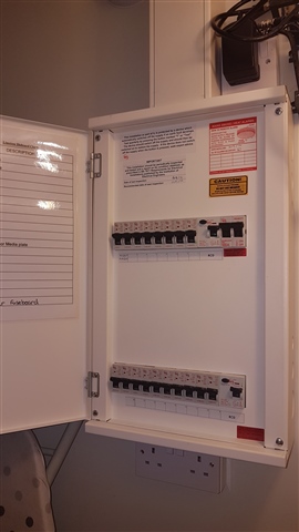
In the wake of the new webinar on inspection and testing, is it still compliant to add a new circuit to an existing plastic consumer unit fitted with type A/C RCD protection and nothing else?

How much 'engineering judgement' leeway do I actually have?

  • You seem to be saying that we don't need to install RCDs for additional protection as only stupid people would be killed by their lack?

  • This demonstrates the need not to drive nails into unknown  territory where there may be concealed pipes or cables. That is like tombstoning, diving into unknown water with possible hidden dangers.

    Solution. Don't bang nails into walls. The regulations can't protect idiots against ALL stupid actions.

    Anyway, if the nail banger is standing on an insulating wooden floor or dry carpet the shock would not be fatal in most cases. How many reported nail banging deaths do we hear about?

    "B.S. 7671 contains requirements for the design, erection and verification of electrical installations as to provide safety and proper functioning for the INTENDED USE." 120.1.

    This does not include damage to fixed wiring by vandal nail bashers.

    Z.

  • I will put that last photo I put on the other discussion on here as well, let's see if any suggestions are forthcoming on how to add an EVSE circuit to this consumer unit that is not particularly old and is in excellent condition.

    No one is planning to install an EVSE circuit to it, but it is a good design project for this forum. 

    So can a EVSE circuit be added to this consumer unit or os it more appropriate to install an additional consumer unit for the EVSE?

  • I will give you a hint 

    https://m2electrical.co.uk/products/40-a-1-mod-dp-compact-rcbo-6ka-b-curve-30ma-type-a/

    but what do you do with it and how, also what else is required?

  • I think that there are already too many final circuits running through single R.C.D.s if I can see the image clearly enough.

    Z.

  •   

    The first impression of that consumer unit is it is better than most, but actually it’s just a six year old dual RCD consumer unit with two Type AC RCDs, however all replacement devices are available for it, so to install a new circuit for EVSE do we alter and upgrade the existing consumer unit or turn the supply off at the DNO isolation switch in the external meter box, cut the tails then install an additional consumer unit?

    https://m2electrical.co.uk/

  • My option would be to install a new dedicated consumer unit for the E.V. charger. I think that the existing consumer unit main switch has enough work to do with all of those existing final circuits as is.

    Z.

  • I know next to nothing about EV chargers or the technology they employ so educate me.

    Is there 230VAC present in the lead between the car and the charger? Or is it just simple whatever-volt D.C. with a couple of comms links to monitor battery charge? If 230VAC is present, then I understand the need for a charger-based RCD.

    Also, what is inside the charger which can send a blinding D.C. current back up your supply cable to your consumer unit? And what could be done to prevent it?

  • Is there 230VAC present in the lead between the car and the charger? Or is it just simple whatever-volt D.C. with a couple of comms links to monitor battery charge? If 230VAC is present, then I understand the need for a charger-based RCD.

    In AC charging systems (Modes 1, 2 and 3 - although mode 1 is no longer found with new vehicles, and Mode 2 is the "granny lead") there is 230 V single-phase or 400 V three-phase switched to the vehicle, direct from the electrical  installation - in Modes 2 and 3, provided safety criteria are met, and for Mode 3, provided pilot comms is established.

    Also, what is inside the charger which can send a blinding D.C. current back up your supply cable to your consumer unit?

    The comms, that is transmitted out on CP and back through PE, is either steady or pulsed DC.

    In TN systems, particularly TN-C-S, with Mode 3 charging, it's easy to demonstrate that N-PE fault between the EVSE and the vehicle could cause the pilot signal to share between N and PE, and this would then put a sufficient amount of DC on the Neutral of the RCD such that some Types of RCD are affected.

    And what could be done to prevent it?

    Nothing without changing the charging standards for EVs - which will do absolutely nothing for the vehicles and chargers out there already.

  • Morning Chris P and everyone else.

    You are wrong when you say BS 7671 is not mandatory.

    APD P requires all installations to comply with BS 7671 in dwellings and common areas of blocks of dwellings. Some of the installation work may be notifiable but all work has to comply;y with BS 7671.

    At the moment APD P has not been updated to the 18th Edition but I am reliably informed it will be soon.

    In any case if you are a professional, qualified and competent electrician you will be designing the installation to BS 7671, installing the installation to BS 7671 and testing the installation for compliance with BS 7671.

    Only your new part has to fully comply with BS 7671 but you should make comments on the existing installation condition in the box provided for that purpose. In my experience there should always be comments there.