The IET is carrying out some important updates between 17-30 April and all of our websites will be view only. For more information, read this Announcement

This discussion is locked.
You cannot post a reply to this discussion. If you have a question start a new discussion

Domestic consumer unit rating with PV and battery storage.

Having read the COP on  Electrical Energy Storage Systems and  completed the IET course on the same subject I had a query regarding the rating of domestic consumer units and switch gear which I addressed by email to NICEIC technical. I also came across an older discussion on this forum but am still no closer to a definitive answer. I've included my findings and would welcome constructive input. 

Post by GKenyon in previous thread

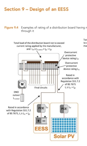
Because an EESS charges the battery as well as as discharging it, you will need to check the rating of the CU is not exceeded. For example, if the CU is rated for 100 A, and there's a 100 A service fuse, and a 16 A output battery storage system - by feeding 16 A in at one end through an OCPD, because that OCPD gets hot it contributes to the total heat load in the CU - therefore the CU should be rated for 116 A.

My question to NICEIC.

Hello
Please can you help with the following.
Domestic installations with PV and/or battery storage.
551.7.2 Where the generating set is connected to either the main consumer unit or via a separate consumer unit via Henley blocks the rating of the consumer units shall be protected by a OCPD InA≥In+Ig(s).
Where In = 100A DNO fuse and Ig(s) = 16A MCB or 2 x 16A MCB's which would be 116A or 132A, what inspection code should be given on an EICR where a standard domestic consumer unit is fitted which has a rating of 100A. Can any allowance be given on connected load being less than 100A or as the regulation relates to the rated current of the assembly and is a "shall" requirement does the load have no influence on the code assigned. 
Answer from Certsure

The Certsure Technical Helpline provides general information and guidance for compliance with the British Standard BS 7671, the Requirements for Electrical Installations, and matters concerning electrical safety within electrical installations designed, constructed, inspected, and tested to BS 7671. Without detailed knowledge of your installation, we cannot offer advice specific to your installation and can only generically provide comments based on the information you have provided.

The intent of the regulation is to ensure that the assembly is not overloaded with the additional generating set, as the main fuse may not protect the assembly if for example the internal busbar is pulling 116A.

Regulation 536.4.202 states: see regulation

From the viewpoint of an EICR, we would be looking for evidence that the assembly is being overloaded, such as burning, distorting and the likes.

The above regulation allows for diversity to be taken into account, so we can exercise our engineering judgement in declaring whether or not the assembly is suitably protected.

We trust that we have answered your current question; however if you require any further information or clarification, then please do not hesitate to contact us either by e-mail to helpline@certsure.com or by telephone on 0333 015 6628

I've read 536.4.202 and am interested on your views on the last paragraph with the shall requirement and how this ties in with the answer given by certsure. 536.4.3.2 is also relevant but has not been mentioned in the reply.

Thanks for your time.

  • Except the sign of Ig wrt  In should be reversed, as the currents should be subtracted, (in some more complex system where charging and generation could be simultaneous present) so that the total is 4A (in the load direction).

    The signs only add when there is a common load is fed from two parallel sources of generation.

    Let us ignore the scope for using generation to also correct the power factor of the system, putting current out of phase with the voltage and  requiring complex maths.

    It would still be poorly worded. But over estimating  the cable size is nothing compared to the aggro of removing, reversing and refitting the protective device when the net current crosses zero.

    Mike.

  • But why? I can see no reason for such a requirement.

    Imagine a plug-in inverter that connects into a socket-outlet final circuit (and, when not connected to the grid, they stop outputting power, so assumed to be "safe" on a plug in some countries).

    Not common in this country, but apparently they do exist in Europe, particularly on the balconies of flats in Germany.

    Some manufacturers abroad have also proposed similar for battery storage (offering "backup" to the relevant socket-outlet circuit by tripping an RCD or similar device in the CU if the mains goes off).

    So, that kind of thing is why 551.7.2 is as it is. And the requirements need to remain in place because of that. However, there's no saying an exception couldn't be made for battery storage systems (as it sort of is with Solar PV by virtue of Regulation 712.551.7.2).

    I feel sure there must have been some mis-interpretation going on somewhere. There seems to be an assumption that an energy storage system is a load AND a source - whereas if actually (to my mind) either a load OR a source - and treating the two different situations distinctly

    Agreed in part. Not mis-interpretation, but requirements for one thing that have an unintended consequence on something else, as I said a couple of days back, and there is no reason why a dedicated circuit for a battery storage system (alone) should have to comply with those requirements, but at present there is no exception.

    However, despite the IET raising this in the CoP since 2017, and despite all those who reviewed the First and Second Editions of that CoP through public consultation as well as committee reviews, it is only now battery storage is becoming more in demand (and some installations have not been done in accordance with the recommendations of the CoP and requirements in BS 7671) that people are starting to see the issue.

    Certainly one on the list for further discussion.

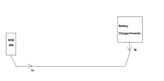
  • Except the sign of Ig wrt  In should be reversed, as the currents should be subtracted,

    Depends on the layout of the circuit - where its such that the grid current and generator current can flow in the same direction at the same time they may well add. E.g.

    But with a dedicated circuit there are no loads when the storage system is in generating mode:

    so I can't see why it should be thought 551.7.2 need be applicable.

       - Andy.

  • so I can't see why it should be thought 551.7.2 need be applicable.

    Sadly, the wording in Regulation 551.7.2 is what it is right now. Drawing diagrams doesn't change that wording, but does illustrate the fact that either

    (a) those words ought to change, or

    (b) the special position of a circuit that only has battery storage connected is somehow excepted from the first part of the Regulation.

  • Wow. I must admit I`d never considered that. In simple terms if you had three single phases at 100A pull each on a three phase supply but one of those 100A was in fact on export then you`d need to redraw the vectors and say make the export vector minus 100A which would skew the N vector well off course? if I understand properly

  • The signs only add when there is a common load is fed from two parallel sources of generation.

    Or a fault in the circuit.

  • Sadly, the wording in Regulation 551.7.2 is what it is right now.

    It's still open to interpretation I feel. There's nothing in the words that I can see that says we have to treat the storage system as a generator when it's not actually in use as a generator, or treat it as a load when it is generating. It says 'a generating set used as an additional source of supply' rather than say 'a generating set capable of being used as an additional source of supply' so I don't see why we can't treat the charging/generating modes separately. It then becomes simple:

    In charging mode, there's just the one load - so it's a simple final circuit with no generation involved so 551.7 doesn't apply at that time.

    In discharging/generating mode, it has no loads directly connected, so it's not a final circuit any more, and so the first indent of 551.7.2 (on the supply side of all the protective devices for the final circuits of the installation) is satisfied.

    Stick another load/sockets on the storage system circuit though and everything changes - it then becomes the sort of tricky situation that bulk of 551.7.2 seems intended to handle and then we do have to go down the Iz ≥ In + Ig route (as perhaps we should consider for distribution circuits too in some circumstances, but that's a slightly different argument again).

       - Andy.

  • In discharging/generating mode, it has no loads directly connected,

    That might be the case if it's a hybrid inverter ... but that's not the only solution.

    However, I'm not 100  % convinced with 'a generating set capable of being used as an additional source of supply' either, because the grid-connected inverter is always connected in parallel when the grid is energized, whether it's exporting or not.

    And to add weight to this argument, Regulation 712.551.7.2 exists to make the situation very plain and simple for Solar PV, without playing semantics.

    The hidden risk with playing semantics, is that only a court might unravel the truth of the matter if things went sadly wrong - in this case, for example, any overcurrent situation where it could be claimed that compliance with the formula for Iz in Regulation 551.7.2 might have saved the day.

    I simply think something similar needs saying for battery storage, plain and simple.

  • Am I right in thinking when using this arrangement it appears to show a split load RCD consumer unit with the EESS and Solar PV on the load side of the RCD. In a situation where all demand is satisfied by the on site generation eg 32A solar+ battery some circuits will have no RCD protection.

    If the Solar PV inverter and battery inverter are mounted 10 m away from the consumer unit and the total load of the installation is being supplied by Solar PV and battery, how is the cable to the consumer unit protected for high impedance fault current. Eg where buried<50mm PVC/PVC cable would require 30mA RCD. Should the inverters be connected to a small consumer unit with overcurrent, short circuit and earth fault current before any cables are buried in the fabric of the building.

    Can suitably IP rated inverters be mounted in areas such as farm buildings where fire protection is required with the use of a 300mA RCD. When in export state any RCD at the origin may have no effect if all energy is supplied from the inverter.

  •  RCD and over current protection at both ends of the circuit.