The IET is carrying out some important updates between 17-30 April and all of our websites will be view only. For more information, read this Announcement

This discussion is locked.
You cannot post a reply to this discussion. If you have a question start a new discussion

Domestic consumer unit rating with PV and battery storage.

Having read the COP on  Electrical Energy Storage Systems and  completed the IET course on the same subject I had a query regarding the rating of domestic consumer units and switch gear which I addressed by email to NICEIC technical. I also came across an older discussion on this forum but am still no closer to a definitive answer. I've included my findings and would welcome constructive input. 

Post by GKenyon in previous thread

Because an EESS charges the battery as well as as discharging it, you will need to check the rating of the CU is not exceeded. For example, if the CU is rated for 100 A, and there's a 100 A service fuse, and a 16 A output battery storage system - by feeding 16 A in at one end through an OCPD, because that OCPD gets hot it contributes to the total heat load in the CU - therefore the CU should be rated for 116 A.

My question to NICEIC.

Hello
Please can you help with the following.
Domestic installations with PV and/or battery storage.
551.7.2 Where the generating set is connected to either the main consumer unit or via a separate consumer unit via Henley blocks the rating of the consumer units shall be protected by a OCPD InA≥In+Ig(s).
Where In = 100A DNO fuse and Ig(s) = 16A MCB or 2 x 16A MCB's which would be 116A or 132A, what inspection code should be given on an EICR where a standard domestic consumer unit is fitted which has a rating of 100A. Can any allowance be given on connected load being less than 100A or as the regulation relates to the rated current of the assembly and is a "shall" requirement does the load have no influence on the code assigned. 
Answer from Certsure

The Certsure Technical Helpline provides general information and guidance for compliance with the British Standard BS 7671, the Requirements for Electrical Installations, and matters concerning electrical safety within electrical installations designed, constructed, inspected, and tested to BS 7671. Without detailed knowledge of your installation, we cannot offer advice specific to your installation and can only generically provide comments based on the information you have provided.

The intent of the regulation is to ensure that the assembly is not overloaded with the additional generating set, as the main fuse may not protect the assembly if for example the internal busbar is pulling 116A.

Regulation 536.4.202 states: see regulation

From the viewpoint of an EICR, we would be looking for evidence that the assembly is being overloaded, such as burning, distorting and the likes.

The above regulation allows for diversity to be taken into account, so we can exercise our engineering judgement in declaring whether or not the assembly is suitably protected.

We trust that we have answered your current question; however if you require any further information or clarification, then please do not hesitate to contact us either by e-mail to helpline@certsure.com or by telephone on 0333 015 6628

I've read 536.4.202 and am interested on your views on the last paragraph with the shall requirement and how this ties in with the answer given by certsure. 536.4.3.2 is also relevant but has not been mentioned in the reply.

Thanks for your time.

  • This discussion is interesting but seems to be a little shy of the actual characteristics of the equipment. Battery inverters cannot supply significant excess current, and have protection built in to prevent this situation which otherwise would rapidly cause electronic failure. Therefore the short circuit condition is not as described, as the inverter MCB can probably never trip, the inverter will simply supply the rated current an very low voltage, or more likely shut down altogether. Therefore the mains MCB will trip too due to the excess current and the supply will not dissipate significant power in the cable, simply rated for the inverter output current.

    In a recent discussion, the problem of connections as shown in Andy's second drawing, was discussed but is probably unsatisfactory due to a different problem. In order to provide power back to the mains, although OK in Island mode, a significantly higher voltage is required to overcome any voltage drop in the connecting cables. The solution is that local generation should connect DIRECTLY to the consumer side of the meter via a dedicated circuit, not as drawing 2 on a local final circuit.

    The lack of RCD protection at this point is then not a problem either, assuming the cable is installed or chosen to make this unnecessary, such as SWA if buried or perhaps in steel conduit. Note that this arrangement also prevents any kind of overload situation of the connecting cable, so the "difficulties" with 536 etc are avoided. Over-current protection at the inverter is not required and "adding" of the protective device current is not required.

  • If the Solar PV inverter and battery inverter are mounted 10 m away from the consumer unit and the total load of the installation is being supplied by Solar PV and battery, how is the cable to the consumer unit protected for high impedance fault current. Eg where buried<50mm PVC/PVC cable would require 30mA RCD.

    An RCD at the grid-end of the circuit will still detect & trip on earth faults even if all the current is provided by the on-site generator - why? because when running in parallel with the grid the on-site generator must not have its own N-PE link - the only path for any earth fault current is via the grid supply's N-PE link - and so the fault current will pass through the grid-side RCD (if only in it's N pole to return to the on-site generator's N). That won't disconnect the generator from the fault of course, but provided the RCD opens N as well as L(s) (as required 551.7.1(ii)) then the on-site generator becomes isolated from Earth (again because it doesn't have its own N-PE link) in effect becoming a separated or IT circuit, so the shock path is broken - so the danger is removed. No need for a 2nd RCD at the generator end (it wouldn't work anyway for faults (other than on the generator itself) as there's no N-PE link on the generator.

       - Andy.

  • Island mode?

  • Thank you.

    Having now appreciated that when the inverters are generating in parallel they are operating in separated or IT mode it makes more sense. Your explanation is a great help.

  •  RCD and over current protection at both ends of the circuit.

    Yes ... and as David says, the arrangement has no load-shedding to prevent large loads being connected.

    The diagram is only to illustrate the principles of Reg 551.7.2

  • Battery inverters cannot supply significant excess current, and have protection built in to prevent this situation which otherwise would rapidly cause electronic failure.

    Whilst this is technically correct, in practice if the inverter manufacturer fails to provide sufficient information to permit compliance with Regulation 419.2 an RCD is often necessary for ADS. This is required at the inverter itself, but it need not be a 30 mA RCD (and perhaps may be time delay depending in disconnection times) unless additional protection is required for other reasons (e.g. cables concealed in building fabric < 50 mm without suitable protection).

  • Having now appreciated that when the inverters are generating in parallel they are operating in separated or IT mode

    No they are not, operating IT mode, they are either connected to the grid (in which case the grid earthing arrangement applies) or they ought to be connected in TN-S arrangement. IT is not recommended for island mode, and Chapter 82 in AMD2 requires a neutral to be formed by earthing after disconnecting the live conductors to the grid.

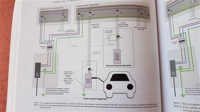
  • One of the vehicles as storage examples in the IET COP Electric Vehicle Charging Equipment Installation 4th edition with RCD protection at both ends of the EVSE and storage batteries circuits. 

    shop.theiet.org/code-of-practice-for-electric-vehicle-charging-equipment-installation-4th-edition

  • Island mode?

    Yes in island mode the on-site generator would have to behave in the same way as the grid supply - i.e. provide a N-PE link and any RCDs would have to be positioned after the generator - but that's a different kettle of fish again from 551.7 as it's no longer in parallel with 'other sources'.

    I guess if you had multiple on-site generators that could run in various combinations in island mode, things start to get even more complicated and but still you'd need to arrange things to have exactly on N-PE link active at any one time and ensure that earth fault currents do pass through appropriate RCDs. Where an EV charge point as been TT'd and is then generating, in island mode the change point would become TN-S from its local electrode and the main installation then becomes TT (if with fortuitous connections to the grid PME Earth), so it can get much more "interesting".

      - Andy.

  • Having now appreciated that when the inverters are generating in parallel they are operating in separated or IT mode

    Probably more accurate to think of them connected in the same way as an ordinary load (if one with -ve power consumption) - i.e. form part of the same system to which they're connected (usually TN or TT). Strictly speaking they only operate as a separated or IT system in the rare event that the RCD trips (and then just until the inverter senses grid loss and shuts down).

       - Andy.