This discussion is locked.
You cannot post a reply to this discussion. If you have a question start a new discussion

Three Phase 230V three wire systems

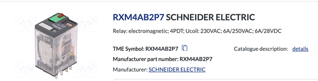
We have a emergency shutdown system on our rig that is wired in such a way the relays always have a minimum of 90v on L2 side of the coil so it is intermittently not opening on ESD activation. I believe this is incorrectly designed as we have a three wire three phase system, no neutral so in theory 110v each phase and 230v across any two phases.

Intermittently when activating the ESD buttons the activation relays will not open because of the constant voltage of anywhere between 90-110v on L2. I am trying to convince my engineering department that this is incorrect and we need to redesign but it is difficult as they don't understand the issue.

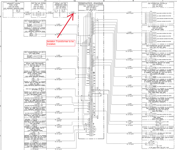
What i would like to propose to temporarily fix the issue is to put in a Isolation transformer and tie down the L2 side to earth of the secondary to give us a 0vL2 and 230v L1. This guarantees the relays will work when intended but i am not 100% sure this is allowed?

Can someone please assist me if at all possible.

  • I do but it depends on the cable type.  I reckon the 1k5 is the relay coil, half a km of wire the thickness of a hair sounds like the actuator, not the wire to it.
    Even in 0,1mm 2 (and any sensible installation wire it will be fatter than that,  even if it had been done in phone wire) so we are looking at something like 0.16 ohms per metre, so to get to 1k5  is  ~ 9 or 10 kilometres round loop and nearer 100km for anything more sensibly wired in 1mm2 I find that unlikely.

    PS sorry capacitance per meter is in the range 10pF to 100pF,  the  lower figures for thinspindly wires well separated, the higher figure core to core in large SWA. 60pF m is a good first stab for lighting twin and earth between adjacent cores. Less between non-adjacent.

    Mike.

  • Yes i am going down the capacitance route now, the cable runs as all wired in series is approximately 600m maybe even more. This is a offshore drilling unit so its 60Hz also. I believe the fact we have a float capacitance and a floating live on L2 is keeping the relay energized intermittently.  This being said it is a very poorly designed system.

    Please ignore the red line isolation transformer part, that is what i am proposing to fit as a temporary measure till our engineering department agree with designing this to incorporate zero volt contact safety relays etc .

    I believe we could install bleeder resistors to cure this issue but again that will need OEM and engineering approval. 

    Would you agree my thoughts are correct and this is a incorrectly or poorly designed critical safety system?

    Please see below drawing of the circuit and the relay fitted.

     AJ,

  • Sorry i should have also mentioned it is wired in 2.5mm ships braided cable. Thank you for the input on this, do you have a website or know in regs where i would find out the capacitance of this. As mentioned i would hazard a guess of a minimum of 600 to a 1000 meters. It is a huge run especially once all connected together in series.

  • Do you mean this sort of stuff

    If so in terms of capacitance per unit length it looks like it should be similar to SY/CY if so, I'd expect a 600metre run to be about 30nF between cores and more like 60nF core to braid. Plus minus 25% or so.

    at 60Hz that is about 40kj ohms to the braid, and 80kj ohms to the other cores. Now that assumes of course that the break when it does not unlock is at the far end, but if the Estop is right next to the coil, then it that impedance is higher as the length of live cable is shorter. But it reallyy depends on the hold in current of the actuator - in some designs the always let go current  may be little as 10% of the always pull in level - once pulled in the magnetic path is a lot shorter.

    In this case data on that exact relay suggests hold in down to 15% of nominal voltage, and the coil is 15k ohms, not 1.5k check your results.

    That suggests it could  hold in even with 20nF ~ 100kj ohms on  a 230V supply

    Personally I'd consider  adding some capacitance ~ 100nF or more in shunt with the relay coils and verifying what the coil voltage actually  collapses to when the most unreliable Estop is pressed using a high Z dmm

    Mike

  • Yes OK davezawadi(at)yahoo.co.uk