This discussion is locked.
You cannot post a reply to this discussion. If you have a question start a new discussion

High voltage supply current limit to not be hazardous live (IEC 61010-1)

I'm working on a high voltage supply (150V) based on a current mode boost converter, the supply only needs to output <1mA at peak load. I want the output of the supply to conform to IEC61010-1 to not be considered hazardous live as I don't want to need to build in any safeguards.

I believe to achieve this, the capacitance on the supply output needs to be under 300nF (Figure 3, 6.3.1.c.1), and the current must be limited to 2mA (6.3.1.b.1) under normal conditions. Under single fault conditions these limits rise.

The current must be kept under 2mA through a 2k resistor to ground, according to Figure A.2, which I believe comes from IEC 60990.

For the current to only be 2mA through a 2k resistor, the voltage of the supply would be pulled down to 4V. This is well under the 60V limit for DC voltages. Does this mean that the 2mA limit no longer applies here? Or because the inital voltage was over 60V, which would lead to a breakdown and allow current to start flowing, the maximum current allowed is 2mA irrespective of the final voltage?

Secondly, the capacitors on the output of the supply will discharge through the 2k resistor leading to an initial spike of current as they are pulled down to 4V. I can't see any way to avoid this, or any limitations placed on this within the standard. Is it only the steady state voltage/current that matters after the 2k probe is applied?

Thanks!
  • but this is not BS7671, it is a standard that regulates the things that plug into, not those that comprise the fixed wiring, and has some ideas that in BS 7671 would be heretical, such as an additional set of voltages that are considered 'safe' during first faults that do not operate any kind of ADS, and some other currents and voltage limits etc that disagree.
    Mike.

  • Yeah, I've been looking at something like that in LTspice also, using a boost converter not a flyback. It would be a high side detection like your first example. The output of the boost converter at the diode/capacitor node would then not be current limited, but there would be two stages of current limiting after that to provide single fault condition coverage to the output of the overall DC-DC converter.

    Unfortunately that means that if a user were to be able to touch the specific area of the circuit where the boost converter output was, they would be zapped by a non-current-limited circuit. As the board will be enclosed in a box in a dry environment (with connectors providing power and communications), is it reasonable to assume that that access to that area of the board isn't something to worry about. So long as the output of the circuit as a whole is limited.

  • The board will be enclosed in a metal box in a dry environment, so the plan is there would be no user access to the high voltage circuits. That said there will be connectors exiting the box carrying signals and power. These lines can't be isolated from the high voltage circuits unfortunately, which is why I'm trying to ensure the high voltage circuits are never hazardous live in case they ever break through to the signal paths.

  • Then if the 150V never reaches the terminals, then ignore what I said earlier, a simple diode clamp on the wires to the accessible terminals to keep the voltage between any pair and any one and ground below 60V or whatever you decide.

    Inaccessible terminals can have any voltage on them you like. Bare mains on spade lugs is fine, inside a box in a place they cannot be touched.
    Mike.

  • What type of connectors are you using ... are they always IP2X, rated (for the conditions in which the equipment is to be used).

    Connectors exit ... do we need to consider fault conditions or accidental damage?

    If the device may be used in, or supply cables in, say, wet conditions, touch-voltages and touch currents at lower values ought to be considered (you mention 60 V, but this would be reduced usually in wet environments) - similarly, it's generally accepted that for immersed bodies there may never be an acceptable "maximum touch-current".

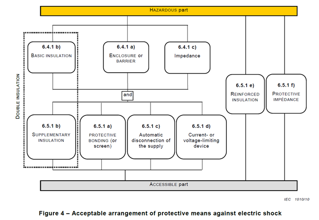
  • Right. So according to figure 4. of the standard, I'd then have a hazardous live source, It would be protected from an "enclosure or barrier" (6.4.1a), and a "current or voltage limiting device" (6.5.1d).

    The diodes you suggested would simply need to comply with 6.5.6. Rated to limit voltage, rated for maximum working current etc.

  • The unit will only be used in a dry environment. And yes, if I'm relying on the enclosure for isolation, then I'll need to ensure that it is resistant to damage. I think that's covered in the standard too. There will be an RS232 serial port on the side.

  • Then if the 150V never reaches the terminals, then ignore what I said earlier, a simple diode clamp on the wires to the accessible terminals to keep the voltage between any pair and any one and ground below 60V or whatever you decide.

    Inaccessible terminals can have any voltage on them you like.

    I would agree with that, but

    There will be an RS232 serial port on the side.

    RS232 ports often don't meet IP2X, either on the equipment, or at the remote end of the cable.

    Also, what if the connected equipment at the other end assumes the RS232 circuits are supplied by SELV or PELV (or ES1 limits to BS EN 62368-1, although note that these do not fully align with SELV and PELV touch voltage and touch current limits)?

  • In terms of sealing against pollution levels, I will ensure all connectors, cabling, and the enclosure are compliant.

    Does it matter if the connecting device is qualified against BS EN 62368-1 or BS EN 60950? If my device is a measurement device to be used in a laboratory, and the PC it's connected to is within that environment also, is it really a requirement for the measurement device to have outputs qualified to BS EN 62368-1? Achieving ES1 compliance is much more involved and would require an actual (basic/supplementary/reinforced) isolation barrier.

    I noticed the other day that according to BS EN 62368-1, the limitations for capacitance at 150V for a node to be ES1 is 41nF, or 300nF for ES2, compared to just 300nF for compliance against BS EN 61010-1. I suppose they are giving extra margin to laboratory equipment operated by more competent users in a more controlled environment?

  • I noticed the other day that according to BS EN 62368-1, the limitations for capacitance at 150V for a node to be ES1 is 41nF, or 300nF for ES2, compared to just 300nF for compliance against BS EN 61010-1. I suppose they are giving extra margin to laboratory equipment operated by more competent users in a more controlled environment?

    There are probably a lot of other differences, including perhaps alignment regarding SELV/PELV, and perhaps one or two other alignment issues of BS EN IEC 62368 series with BS EN 61140.

    Does it matter if the connecting device is qualified against BS EN 62368-1 or BS EN 60950?

    No, but it might matter if connecting your device defeats ES1 or SELV/PELV provisions in the connecting device, particularly if it might lead to someone getting hurt, or perhaps a fire.

    This makes the situation not easy to risk assess from a manufacturer's perspective. I agree it's not 100 % clear either.