This discussion is locked.
You cannot post a reply to this discussion. If you have a question start a new discussion

TNC installation - Continental Europe

  1. Hi,

I am looking at re-wiring a small apartment on the continent. The supply to the building is a TNC.

I was quite surprised to find a 4 core 6mm cable coming into the building from an underground cable, with the 3 phases landing into 80A fuses and the neutrals twisted together with an aged bit of tape around them. There are then multiple 4mm cables that connect to the secondary side of these fuses, which go off to the various properties.

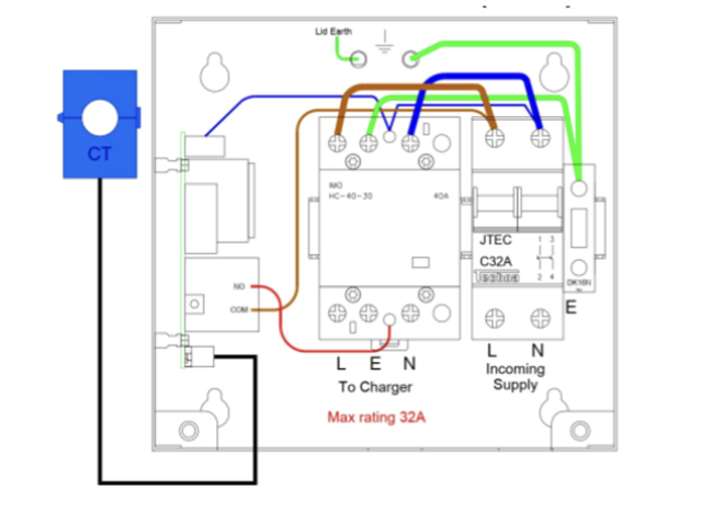
The properties themselves have a consumer DB, with the phase conductor landing in a 32A MCB. The neutral then lands into the neutral bar, with a link to the earth bar.

I just wanted to clarify the following. 

Q1: 

When upgrading this apartment, I obviously want to use RCDs. I believe in order to do this, I would need to land the incoming neutral into a suitable connector, which then links to the neural terminal of the RCD and also the earth bar - this would then give me a TNC-S earth and neutral. The neutral output of the RCD is then in essence measured and compared to the phase conductor for subsequent outgoing circuit protection. 

Q2: 

I am assuming that the supply authority rely solely on the consumers “main switch” which is in essence an MCB to ensure the cable between the suppliers main feed and the property isn’t overloaded, because the suppliers fuses are not rated to protect the 4mm cable that comes into the property. I believe they have rated the fuses high enough to cope with the maximum demand for the connected properties. 

This would then mean, that the phase conductor needs to land into this MCB before the RCD. Is a single pole MCB really the best choice, or should I look to use a double pole MCB that disconnects the phase and the neutral conductor, and if so, what then happens to the earth?  

Obviously all of this falls outside of BS7671, because this standard doesn’t apply on the continent. I am just looking to clarify my understanding. I have actually looked at various installations and all of them are the same. The standard of wiring and associated safety devices/methods doesn’t even compare to what we do in the UK.  

I have also looked at using a local electrician - really not an option considering the state of some of the installations I’ve seen! 

Thanks. 

Parents
  • Would the install of a matt:e at the start of the installation reduce the likelihood of an open PEN?

    It wouldn't reduce the likelihood of an open PEN occurring, it might provide a bit of protection for your installation by disconnecting everything (including the Earth) if it did happen though.

    That said, if there are any shared metallic services with the rest of the building, it's likely to be defeated by main bonding etc. re-introducing the hazardous voltage from other parts of the building. Also most of the open PEN detectors work by measuring L-N voltage - if the supply system is as dodgy as everything else and you get large voltage variations in normal use - which might potentially fool the device into thinking there was a PEN problem when there wasn't - so it might be prone to nuisance tripping.

    Also the risk/benefit is probably a bit different to an EV - inside a building you can usually achieve a half decent equipotential zone so the risk of shock from a broken PEN event is much reduced anyway - while on the other hand you're introducing a set of mechanical contacts in the earthing system which almost inevitably will be less reliable than a single bolted joint.

       -  Andy.

  • Hi Andy, 

    I doubt there is any bonding within the building as such to other services. There are definitely no bonding connections to water I know this much.

    The main incoming supply I think would land directly into the matt:e with the N-E link being made across a DIN rail connector, using the model below: 

    The L&N would connect to the incoming supply terminal, with a link from the N to the E. These 3 connections would then be switched via the contactor, providing a “protected” L,N,E connection. This would then land into the DB as normal, with the E straight to the earth bar and the L&N through a 2 pole RCD. 

    Agree that voltage fluctuations may trip the matt:e device off, however i don’t foresee this being an issue. The supply voltage is pretty consistent and stable, the only reason for using the matt:e would be to add an additional layer of “protection” against lost/open PEN. As mentioned initially, the N conductors from all properties are all twisted together with a bit of tape around them - no really a solid bond as they are floating in free air! 

    Thanks. 

Reply
  • Hi Andy, 

    I doubt there is any bonding within the building as such to other services. There are definitely no bonding connections to water I know this much.

    The main incoming supply I think would land directly into the matt:e with the N-E link being made across a DIN rail connector, using the model below: 

    The L&N would connect to the incoming supply terminal, with a link from the N to the E. These 3 connections would then be switched via the contactor, providing a “protected” L,N,E connection. This would then land into the DB as normal, with the E straight to the earth bar and the L&N through a 2 pole RCD. 

    Agree that voltage fluctuations may trip the matt:e device off, however i don’t foresee this being an issue. The supply voltage is pretty consistent and stable, the only reason for using the matt:e would be to add an additional layer of “protection” against lost/open PEN. As mentioned initially, the N conductors from all properties are all twisted together with a bit of tape around them - no really a solid bond as they are floating in free air! 

    Thanks. 

Children
No Data