This discussion has been locked.
You can no longer post new replies to this discussion. If you have a question you can start a new discussion

Adiabatic problem

Sorry but brain not working this evening and can't get an adiabatic equation to give me a reasonable answer

PFC=12.2Ka

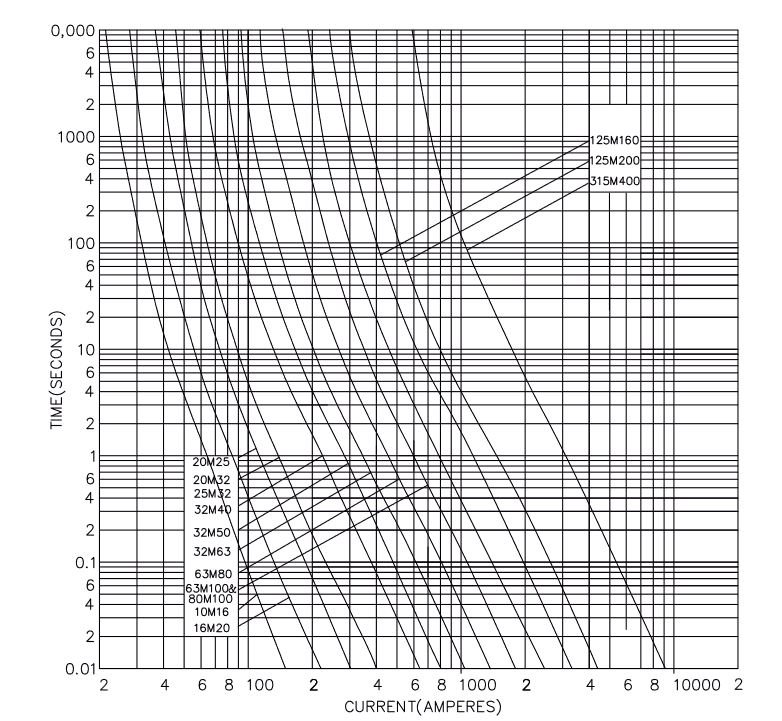
OCPD BS88-2 E 100A  might be 80A but disconnection should be 0.1 at those fault currents

k=115 ie copper sleeved conductor

I'm getting over 30mmCSA main earth which doesn't seem correct

Thanks

  • Are you using the correct value for I? Please see the definition of I. 543.1.3

    Z.

  • That is because disconnection of a BS88 100A fuse at 12kA will be a heck of a lot faster than 5 cycles of mains.

    Try page 22 of this PDF for the values directly as a 'bullrush' plot, or squinting at a curve like one of these will give you an idea of how fast things happen - once you get to a PSSC about 10-20 times the nominal  never blow rating you are looking at current being interrupted in less than one half cycle of mains (0.01 secs).
    And it is better than that - the current may not cut off for so many milliseconds, but for the last few while molten metal is moving and an arc is forming, there are already some extra milli-ohms in the path, and so the fault current is rather below the full PSSC.
    Once you allow for less than 1/10th the energy you will probably land between 6mm2 and 10mm2, which may be closer to your expected value.

    Regards Mike

  • Does Table 54.7 help?

    Z.

  • Thanks for that; it's for an EICR code with a 10mm csa MEC. Normally I'd use that table for any installation design

  • that's helpful at puts my mind at rest, it's the bit of the time curve not in the regs many thanks Mike

  • Once things get really fast the 'time to blow' curves are not really much uses, as the fault cannot be reliied upon to come on at the zero crossing and present a nice sinusoidal half cycle, so the total energy in joules per ohm in the fault path, or I2t becomes more helpful, as that is an integral of the thing that will do the damage to the fuse link and anything else in the loop in an I2R = watts

    I2R* t = joules = total heating energy sort of way. (only approx, R changes as it heats up...)
    Then for non easy waveforms, to estimate the damage done we tend to look for the bullrush plots. Each stalk is a fuse rating, and the bottom of the bullrush 'head' can be seen as the point of no return -  if you get this much energy in , it has started to melt the element, and will open circuit soon after, while the top of the 'head' represents the maximum  amount  of energy that will be let-through - and that is voltage dependent, as it is the extra time for the arc to be stretched to extinction as the metal burns back from the initial point of breaking.

    (if you want to cascade fuses and always want the lower rated one to blow first - think sub mains an so on,  the top of the bullrush representing the lower valued  fuse needs to be below the bottom of the head of the bigger fuse that is the 'death or glory' back up)

    Note that the rule of thumb of a ratio of  2.5 to 3 in current rating between cascaded fuses to get reliable discrimination suits the lower rated fuses better, and a 3 :1 current rating is a 9:1 let through energy if nothing else changes - but it does, because bigger fuses are made quite differently inside, more of a foil ribbon or a perforated lace than a fuse 'wire' as such.

    Mike