This discussion is locked.
You cannot post a reply to this discussion. If you have a question start a new discussion

High earth leakage current on earth bar from mobile telecommunication's equipment

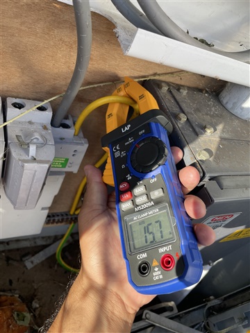
I'm reviewing a mobile infrastructure power system where we have recorded (using a clamp meter) 16A on the MET earth and similar readings on the various bonds terminated onto a common 8 way copper bar earth bar. The site has a 300mA RCCB installed at the TN-C-S source which operates fine as expected however the high current running through the exposed copper earth bar in the meter cabinet is a concern. 

It's worth mentioning that the primary load is mobile network equipment which includes rectifiers and understandably will produce earth leakage from the DC systems. I suppose this would be considered 'planned' earth leakage, however the potential for electric shock from an exposed copper bar cannot be ignored.

I had assumed the IET Guide to Data Centre Power Systems would have some solution to DC earth leakage issues, however this has not yet been formally published. I have encountered high earth currents in a previous project (rail) which resulting the DNO repairing a cable joint in the street however this site is rural and the DC tech seems to be the prime suspect. Is there an IET guidance on how this should be dealt with?

**UPDATE**

The final outcome to this was a broken neutral conductor in the supply cable. When the DNO removed the LV earth link to separate the LV & HV earthing systems in line with G78 the supply was completely lost which identified the the system had been using the combined earth system as a return path. The supply was rewired back to the nearest joint and problem solved. 

Parents
  • If you're using conventional clamp meter, then I doubt it's capable of registering d.c. components anyway as the clamp mechanism usually forms a single-turn transformer, which won't pass d.c..

    The other thought, as it's all mounted on a HV pylon, is that what you're seeing is a.c. leakage from the HV lines - using the LV Earth as an additional  electrode as it were (and one that's to some extent remote from the line of the pylons so less susceptible to a rise in earth potential due to the HV system).

    I wouldn't expect parallel N currents to reach 16A without an open PEN. But I could be wrong!

    A lot of rural LV systems are single-phase - so there might not be any cancelling. The picture might suggest a 3-phase head (with at least one phase unused) which may or may not mean a 3-phase LV system (a lot of the newer work uses 3-phase cables, in anticipation of future upgrades, but still connected to a single-phase transformer for the present). Plus a lot of rual loads can be quite lumpy - e.g. from storage heating or farms at milking time.

       - Andy.

Reply
  • If you're using conventional clamp meter, then I doubt it's capable of registering d.c. components anyway as the clamp mechanism usually forms a single-turn transformer, which won't pass d.c..

    The other thought, as it's all mounted on a HV pylon, is that what you're seeing is a.c. leakage from the HV lines - using the LV Earth as an additional  electrode as it were (and one that's to some extent remote from the line of the pylons so less susceptible to a rise in earth potential due to the HV system).

    I wouldn't expect parallel N currents to reach 16A without an open PEN. But I could be wrong!

    A lot of rural LV systems are single-phase - so there might not be any cancelling. The picture might suggest a 3-phase head (with at least one phase unused) which may or may not mean a 3-phase LV system (a lot of the newer work uses 3-phase cables, in anticipation of future upgrades, but still connected to a single-phase transformer for the present). Plus a lot of rual loads can be quite lumpy - e.g. from storage heating or farms at milking time.

       - Andy.

Children
No Data