The IET is carrying out some important updates between 17-30 April and all of our websites will be view only. For more information, read this Announcement

This discussion is locked.
You cannot post a reply to this discussion. If you have a question start a new discussion

CT1 and CT2

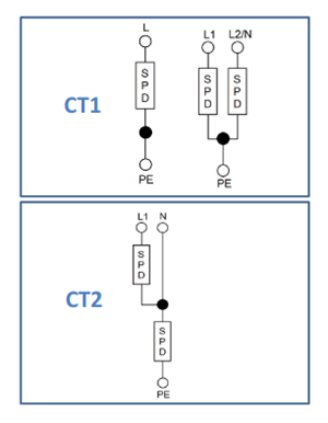
The connection of SPDs using CT1 appears to provide protection only in common mode. That seems be the normal method employed. However, looking at CT2 am I correct in assuming that the clamp voltage would need to be very much less as the protection is provided across the conductors supplying load components? It seems to me that CT1 is for lightning and CT2 more for overvoltages derived from switching???

  • As I see it both CT1 and CT2 limit voltages both between live conductors and between live conductors and Earth - I agree the arrangement is different - so in some circumstances you have two SPDs in series to get a particular effect (L-N clamping in CT1 and L-PE clamping in CT2) but as long as the resulting 'let-through' voltages are still acceptable the protection should still be there. The alternative would be to use three SPD triangle fashion directly between all thee wires (L/N/PE), but that doesn't seem to be necessary.

    For me the difference in usage between CT1 and CT2 is the consideration of the result of the L SPD failing to short circuit - if it's connected L-PE and the short can't cause ADS (e.g. because it's TT and upstream of the first RCD) things can turn nasty - so that's avoided with the CT2 arrangement.

       - Andy.

  • Do not confuse surge levels one and two (or three or four )with surge arrestor configurations one and two. 

    Note I am not using Arabic or Roman numerals just yet deliberately - and there are also classes of insulation and ADS method 0, 0A 1 (earthed) and 2 (double insulated) to be confused by.

    It would be much easier if for new concepts we did not insist on restarting the count from 1 or A but began instead at unique multiples of perhaps 500 or 23 or almost anything really. But we do not.. This leads to similar silliness as our B type RCBO with A type RCD performance.

    Back to the chase...

    There are 4 levels of over voltage 1,2,3,4  from the 13A plug out to the overhead line, although it is a bit arbitrary, as in some cases there is a direct connection

    https://www.cui.com/blog/understanding-iec-overvoltage-categories

    But there are also configurations of surge suppressor CT1 and CT2 that are as Andy described above.

    Arguably either of these may reduce a level IV over voltage into a level II or III but that has little to do with the CT1 CT2 wiring configuration of it and is all about the breakdown voltage of the suppression elements and the inductance of the wiring to them.

    Mike.

    (we do seem to like making things deliberately awkward and then wonder why folk get confused.)

  • I think I am one of those confused folk Mike! So, say we have an arrangement as CT1, each SPD having a clamping voltage of say 1KV, is it reasonable to assume the protection level afforded between the live conductors is 2KV?

  • a guarded yes,

    For CT2, neither line is ever more than Vclamp from PE at the point of surge protection, and at worst L may be going up by 1kV while N is going down so then the L-N difference is indeed  2* Vclamp,  - though just as often they could both see a  jump in same polarity so the LN difference may be small even if both arrestors are clipping relative to PE

    But of course as you move along the cables and away from the surge protector towards the origin of the over-voltage, then  voltage  slopes due to Mr. Ohms law and even more confusingly the effects of  V= L*di/dt  grab you in a rather rate-of-rise time dependent way.

    And V clamp is only that 1kV single figure at the crest of a current pulse with  very particular test waveform, it is not a level at which a flat-top is always guaranteed.

    Mike.

  • Could you tell if this is CT1 or CT2? According to Hager it is CT2.

  • Hard to tell for sure - it all depends on the internal wiring of that 4-module SPD carrier on the right. But given one of the SPD modules is a different colour, I suspect the N-PE one is of a different type (technology) which would be more usual for a CT2 arrangement.

       - Andy.

  • To be certain you need to remove the cartridges and use a multi-meter to "buzz out" the cross;links between the various devices.

    I'd hope Hagar knew their own product but that is how I'd verify it.

    Mike.

  • Also I think Hager were originally French - so are well used to TT installations (the norm in France) - so would expect their product to be TT compatible (i.e CT2).

       - Andy.

  • TT is not exactly unknown in the UK, you just need to go outside the towns and cities. There are plenty of farms with TT 3 phase supplies from meandering 11kV overheads with a transformer on an H-pole in or just outside the boundary - and those are exactly the sort of places where a CT2 surge arrest makes sense (along with a multiplicity of time delay 100ma or 300mA RCDs ... and a little fence or walled off region around the earth electrodes to keep the animals off it.)
    M.

  • The reason I ask about the series arrangement is that the overvoltage withstand requirement, Uw, for equipment as set out in Table 443.2 is for live conductors to earth. In a CT2 connection could the clamp voltage to earth be twice the individual SPD clamp voltage or is the connection to neutral an effective voltage divider?

    So say an overvoltage is in the order of 2KV line to earth. A CT2 method is employed with a 1.5KV SPD between line and neutral and a 1.5KV SPD neutral to earth. Given the earthed neutral, will the line to neutral SPD short?