This discussion is locked.
You cannot post a reply to this discussion. If you have a question start a new discussion

Inverter voltage measurements don't make sense: phase voltage to earth is higher than the line and DC + to earth not equal to DC - to earth

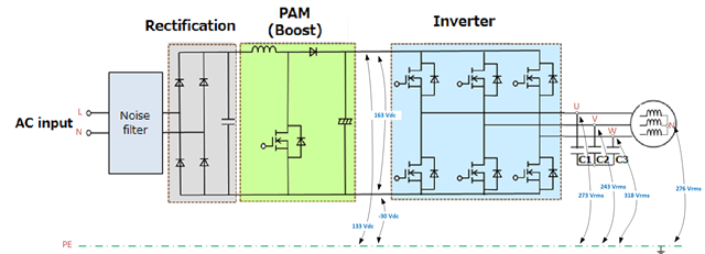
I am trying to get the inverter running and for 163 Vdc in an open-loop, I am measuring line voltage (Vuv, Vvw and Vwu) 76 Vrms which is ok.

But when I measure Vu-earth I get 273 Vrms, Vv-earth = 243 Vrms and Vw-earth = 318 Vrms.

Even stranger is when I measure DC bus + to earth which is 133 Vdc is DC - to earth is -30 Vdc.

Voltage from the load neutral to earth is 276 Vrms.

Schematics and values are shown below:
Why am I measuring this?

I would expect to measure DC + and DC - to earth to be equal and phase voltages to be line/sqrt(3) and neutral to earth to be zero.

Kind regards.

Parents
  • Your diagram doesn't show any part of the circuit connected to Earth.

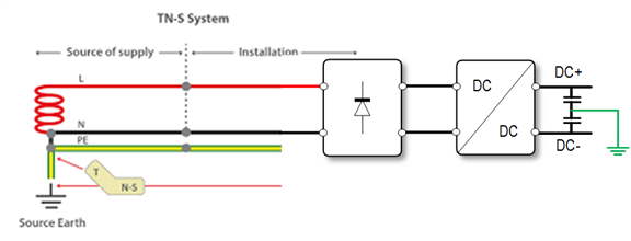
    Wouldn't the AC input N on the LHS normally be Earthed somewhere towards the source? So perhaps not really floating, but certainly the d.c. side will be somewhat detached from simple Earth potential by the rectification diodes.

       - Andy.

Reply
  • Your diagram doesn't show any part of the circuit connected to Earth.

    Wouldn't the AC input N on the LHS normally be Earthed somewhere towards the source? So perhaps not really floating, but certainly the d.c. side will be somewhat detached from simple Earth potential by the rectification diodes.

       - Andy.

Children
  • Wouldn't the AC input N on the LHS normally be Earthed somewhere towards the source?

    That's my biggest concern for grounding the mid-point or anything else in the converter. I am supplying a converter from a single-phase TN-S source. In all cases I looked at, they use a three-phase system feeding a recertifier, and if I ground the mid-point there is no direct part between the input phase and the ground. But in a single-phase system, one of the input phases is grounded.