This discussion is locked.
You cannot post a reply to this discussion. If you have a question start a new discussion

Inverter voltage measurements don't make sense: phase voltage to earth is higher than the line and DC + to earth not equal to DC - to earth

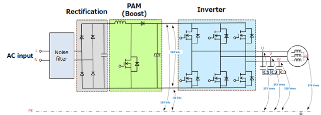
I am trying to get the inverter running and for 163 Vdc in an open-loop, I am measuring line voltage (Vuv, Vvw and Vwu) 76 Vrms which is ok.

But when I measure Vu-earth I get 273 Vrms, Vv-earth = 243 Vrms and Vw-earth = 318 Vrms.

Even stranger is when I measure DC bus + to earth which is 133 Vdc is DC - to earth is -30 Vdc.

Voltage from the load neutral to earth is 276 Vrms.

Schematics and values are shown below:
Why am I measuring this?

I would expect to measure DC + and DC - to earth to be equal and phase voltages to be line/sqrt(3) and neutral to earth to be zero.

Kind regards.

Parents
  • On  a single phase system with a bridge, alternate sides of the smoothing capacitor are connected to mains L and N as the cycle reverses. Again, neither side is grounded, and the mid point is not safe to ground either.

    Now, to make it clear how to visualise it, if  instead of L and N you had two lines in perfect anti-phase ( a split phase with a +L and a -L if you like) then the mid point of that would match the mid point of the DC rail. So shifting our reference frame by grounding the neutral then the mid point of the DC bus becomes centred about the centre of the mains, so about 120V RMS or so wrt neutral, and of  course the useful ends of the DC bus see the same AC plus a DC offset.

    But neutral is not earthed, rather it is offset by a small load dependent voltage, that is the drop in the neutral wiring, much as the live is rather less at the load than at the origin so nothing is properly fixed relative to ground at all.

    Note, re your comments on 3 phase, that if you take the mid point of two capacitors off a six diode bridge and force it to neutral you do not have the same circuit as I described. Instead of 300 Hz ripple and a bouncing centre you now have two completely independent single phase rectifiers, each with 3 diodes feeding one cap and 150Hz ripple. The ripples on the two caps are offset by 1/6 cycle so the effect is not dissimilar, but there is a 300Hz current flowing in the neutral and the DC bus voltage is not quite the same. Both flavours with and without neutral do exist in the wild but are not quite equivalent.

    Mike

  • Hi Mike, thank you for the explanation.

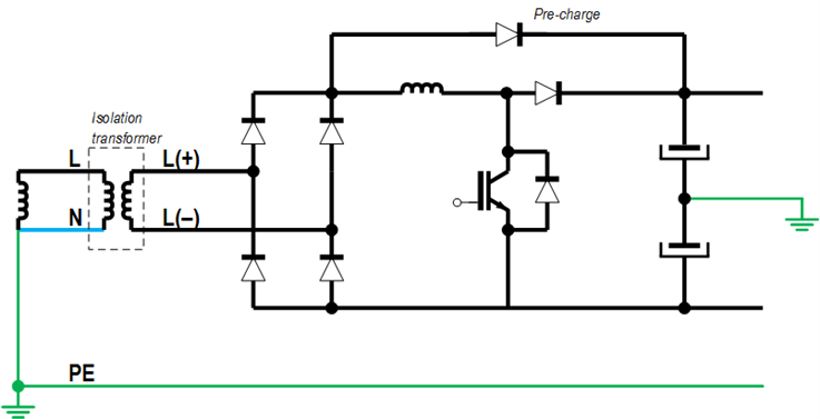
    So if I use an isolation transformer at the input, I could ground the DC link mid-point? In that case, I would have L(+) and L(-), instead of L and N.

  • Yes, that will work.
    Can  I ask what you intend to do with the grounded centre ?  Clearly as drawn there, any inequality in the capacitors will mean that the above and below sides of the DC bus cease to be equal, and any attempt to draw or inject current from or to that point is also likely to lead to centering imbalance issues.

    Of course if the isolating transformer has a fully floating secondary, as you have drawn, so you are at equally liberty to ground any one point on the secondary side, and the voltages of the rest of the design will work as before and the voltages simply fly around that. However in terms of understanding circuit operation, ,and not having EMC problems from accidental antennas with large dV/dt some points are more sensible to earth than others ;-)

    Mike.

  • Can  I ask what you intend to do with the grounded centre ?

    I am trying to measure common-mode voltage and most of the papers i found [1] [2] [3] [4] use grounded mid-point so I am trying to replicate the same measurements. I assume they all use rectified three-phase voltage or variation to get a DC link, while I use rectified single phase.

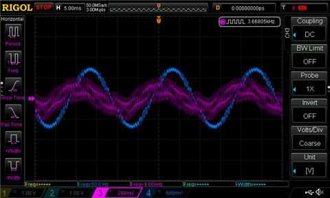
    When I tried to measure a common-mode with un-grounded converter (as shown in my initial post) I measured a 50 Hz signal on the oscilloscope superimpose to the common-mode voltage weveform.

    I am hoping that by properly grounding the inverter (i.e., DC link mid-point) I will get the same results as in the papers (no superimposed AC signal). Because I don't see any other difference in my set-up

  • Ah well, in the lab when initial testing the inverter part in isolation the DC bus comes from a regulated DC supply  with all sorts of safety interlocks and fast shutdown, and is much more complex than the off-line version in the final product. Similarly when testing the off-line PSU part, initially the inverter may be replaced by another adjustable  load that is easier to manage.

    Once it gets off the bench and is being integrated then pairs of probes and differential measurements are your friend.

    By CVM I assume you mean the movement of the motor star-point - assuming a star load and not a delta, relative to some notional DC bus centre. Ideally it will be well centered over a full cycle but will precess at the cycle frequency and probably in reality be a few volts off-centre.

    In your shoes I'd create that load centre from 3 equal loads on the phases,  and then AC couple it to one side of a diff-amp, and put the bus voltage, top, centre or bottom, to another probe, and then subtract.

    Please take care, experimentally  this is not easy stuff to do safely - hence the first reference you gave - the IEEE paper - being about modelling it, not measuring it.

    LT spice or something more powerful is your friend for initial design verification, it saves a lot of red faces.

    Mike.

Reply
  • Ah well, in the lab when initial testing the inverter part in isolation the DC bus comes from a regulated DC supply  with all sorts of safety interlocks and fast shutdown, and is much more complex than the off-line version in the final product. Similarly when testing the off-line PSU part, initially the inverter may be replaced by another adjustable  load that is easier to manage.

    Once it gets off the bench and is being integrated then pairs of probes and differential measurements are your friend.

    By CVM I assume you mean the movement of the motor star-point - assuming a star load and not a delta, relative to some notional DC bus centre. Ideally it will be well centered over a full cycle but will precess at the cycle frequency and probably in reality be a few volts off-centre.

    In your shoes I'd create that load centre from 3 equal loads on the phases,  and then AC couple it to one side of a diff-amp, and put the bus voltage, top, centre or bottom, to another probe, and then subtract.

    Please take care, experimentally  this is not easy stuff to do safely - hence the first reference you gave - the IEEE paper - being about modelling it, not measuring it.

    LT spice or something more powerful is your friend for initial design verification, it saves a lot of red faces.

    Mike.

Children
No Data