This discussion is locked.
You cannot post a reply to this discussion. If you have a question start a new discussion

Where can a PV array be connected?

I suspect that a PV array would normally be connected between the meter and the first DB, but can it be connected more peripherally please?

The most suitable area of roof is at the opposite end of the premises from the electrical origin. However, there is a small DB with spare ways adjacent to the loft space. It supplies one lighting and one socket circuit and is seldom significantly loaded. The distribution circuit from the main DB is 16 mm² singles (with the live conductors being sheathed). As far as I can see, it travels through under-floor voids and is boxed in with other services as it ascends in a bathroom so RCD protection is not required. If the inverter can be situated in the loft space then only a short length of AC cable would be required.

This is what I have in mind.
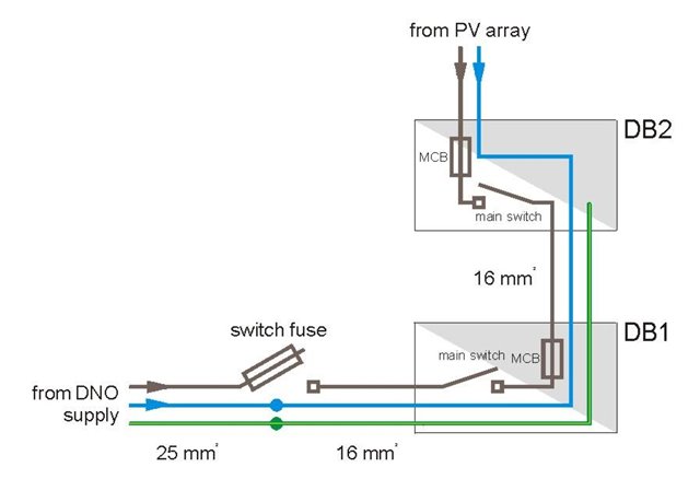
  • Ideally you need to avoid having anything else on that submain so you can isolate the inverter. Can the light and socket be transferred to another circuit ? Electrically it will work of course, but because the direction of voltage drop is reversed it all gets a bit complex and is not recommended.
    M.

  • In principle the AC side of the invert can be (and often is) connected to DBs hanging off submains. The inverter will need to be on its own circuit from the DB (not sharing a final circuit with any current-using equipment) - so isolation (either by CU MCB or local rotary isolator) usually isn't an issue.

    Overload protection needs some thought since some conductors (and switchgear) will potentially be fed from two sources - so the ordinary upstream (from a grid perspective) overcurrent protective devices don't necessarily provide adequate protection any more. E.g. a 100A rated DB which can also perhaps source 16A from the inverter won't any longer be protected from overload by the 100A DNO fuse (or the submain OPD) - and that's likely to be the case whether the PV is connected though an existing DB or a new dedicated one. Where the PV output can be consumed on-site there's also the issue that in terms of heat dissipation from MCBs etc the 16A (or whatever) from the PV has to be counted twice - once from it's own MCB and again as the current goes out again via one of the other circuits - all in addition to the 100A (say) from the grid. Having the PV connected to a lightly loaded CU with an grid-side overcurrent protective device significantly lower than the DB's rating, if anything is likely to help considerably with these problems.

      -  Andy.

  • Mike, thank you. I hadn't thought about voltage drop, but now I have a mental picture of electrons meeting in the middle and having a sort of push-of-war.

    Concerning isolation, I realise that there would have to be warning notices on the various DBs about two sources of supply.

  • Andy, thank you. I was quite surprised to see the size of the distribution circuit's cables so they won't be a problem.

    At the moment, the DNO's fuse is 80 A and the switch fuse is either 63 A or 80 A so no problem there.

    The whole idea is, of course, to reduce consumption, not boost it! One of our neighbours had a PV set up installed last month and his consumption from the grid has already halved.

  • Thank you to Mike and Andy as ever for their opinions even if they do not entirely agree. The bottom line will be to leave it to the contractor, but in the mean time, any other thoughts folks?

  • Are the MCBs suitable for being back fed?

    Is RCD protection required?

    If an RCD is required, does it need to be double pole?

  • I don't see why the MCBs should not work backwards, but I am not so sure about RCDs. As mentioned, the distribution circuit does not require RCD protection, but it would mean that the other boards would need to have RCBOs for the final circuits rather than be split boards.

    The main issue is that if the PV output had to go all the way back to the origin, the run would be 60 - 70 m.

  • It cannot be assumed a protective device in a consumer unit can be back fed, it definitely could be an issue with an electronic RCBO.

    Also if an RCD is required for additional protection it has to be double pole, so a single pole RCBO would not be permissible.

  • So long as the inverter stops generating when synchronisation with the mains is lost, the question of which way the current is flowing it not so important. When the thermal part or the RCD part causes contacts to open, the inverter side is safe, after the shut off time.

    But that will be longer than the breaking time alone so ADS times need a re-visit.

    It is much more serious with an inverter capable of island operation, as then the side you may expect to be dead may still be very much alive but just out of phase .

    Mike

  • so ADS times need a re-visit

    If the cables went all the way back to the origin, they might have to be pretty substantial to meet the minimum Zs; but if they went only part way wouldn't that issue go away? Put another way, you would want the inverter supply to have an R1 + R2 at a comparable value to Ze, which may be difficult to achieve.